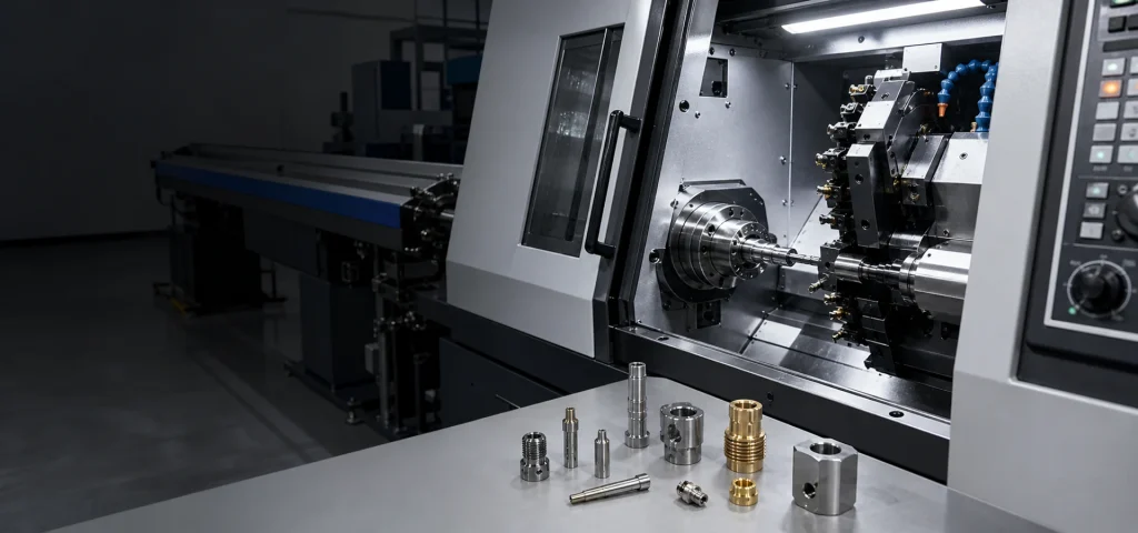
CNC turning concentricity and runout are not interchangeable notes. On a shaft or bushing, circular or total runout to a datum diameter is what most shops can check with a V-block and indicator. ASME Y14.5-2018 removed concentricity as a geometric characteristic, so new drawings should use runout or position. ISO 2768-1 (1989) still covers unspecified sizes, not axis relationships. Call the datum on the journal that locates in the assembly, name the runout value, and say whether you will accept an indicator check or a CMM report. If the drawing only says “concentric,” the China factory has to guess the method.
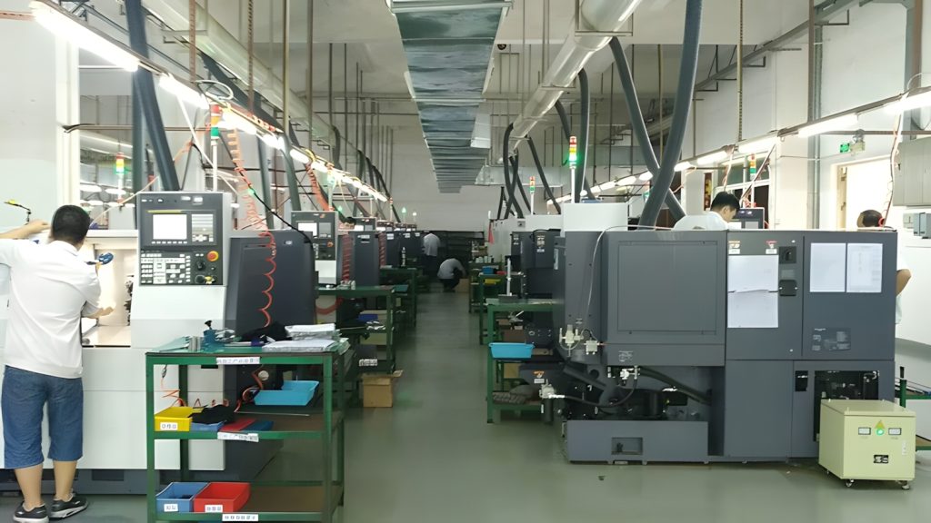
You are dimensioning turned parts for a US or EU print that a Dongguan lathe cell will quote. This page is the specification and inspection frame for coaxial features. It is not a process-choice page for milling, Swiss, or mill-turn.
Bring the STEP and PDF. Mark which diameters locate, which spin, and which only look round.
Key takeaways
- Prefer circular runout or total runout to a datum axis on rotating parts.
- Use position when you care about the axis, not the spinning surface.
- Do not put concentricity on a new ASME Y14.5-2018 drawing.
- Name the inspection method next to the control, not in an email.
- Tight runout on a diameter you reclamp is a process fight. Change the datum or the setup, not only the number.
What runout actually controls on a turned part
Runout is a surface control while the part rotates about a datum axis. Circular runout is checked in a radial or axial slice. Total runout is checked along the cylinder or face.
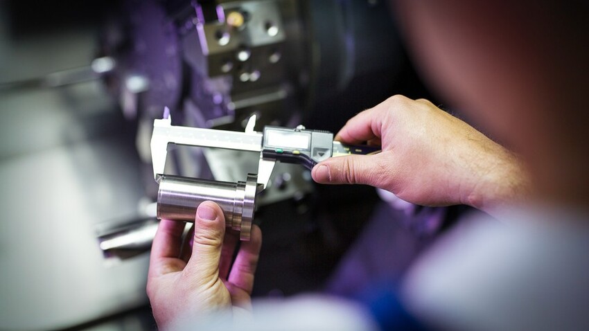
That is why runout matches bearings, seals, and pulleys. An indicator on the journal, part rotating on datum diameters or centers, tells you whether the surface wobbles. NIST manufacturing metrology work in 2024 still treats this kind of measurement as a planned method (NIST).
If you only needed the size of the journal, a micrometer would be enough. Runout shows up when that journal must spin true to another diameter or to centers.
Circular runout in a radial direction is the everyday shaft call. You rotate the part and read the indicator on one belt of the cylinder. Total runout asks that entire cylinder (or face) to stay inside a tighter surface story. Total runout is harder on a long journal, especially when L/D is high and the part can taper.
Runout does not replace size. An Ø20 h6 journal can meet size and still wobble relative to datum A. It can also meet runout and miss the fit. Put both on the functional diameters. Leave reliefs on a general class such as ISO 2768-m.
Face runout matters on shoulders that locate a bearing. Axial circular runout on that face is the control. A pretty OD with a wobbling shoulder still knocks the stack.
Do not use runout on a feature that never rotates in use and is not inspected by rotation. Two press-fit bores in a housing that must share an axis are often a position problem, even if the shop turns them. Match the control to how you will check it and how the assembly loads it.
CNC turning concentricity and runout compared with position
CNC turning concentricity and runout get quoted against position because buyers still mix the three words.
| Control | What it targets | Typical shop check | Best for | Watch-out |
|---|---|---|---|---|
| Circular runout | Surface variation in one slice while rotating | Indicator, V-block or centers | Bearing journals, seal diameters | Does not replace a size limit |
| Total runout | Surface variation along a cylinder or face | Indicator swept along the feature | Long journals, faces that must run true | Harder on a reclamped part |
| Position (axis) | Axis location to a datum axis | CMM or a derived axis | Bores that must share an axis without spinning in use | Needs a clear datum frame |
| Old concentricity note | Derived median points (ASME pre-2018) | Often CMM, often argued | Legacy prints only | Easy to misread as runout |
Bottom line: if the part spins, specify runout; if two axes must share a zone and the part does not spin in use, specify position.
ASME Y14.5-2018 is the US drawing standard that dropped concentricity and points you to runout, position, or profile instead (ASME Y14.5). Keep ISO 2768-1 (1989) for the sizes you did not otherwise limit (ISO 2768-1).
A second comparison helps on mixed parts.
| Situation | Control to put on the PDF | Cell implication |
|---|---|---|
| Two journals that spin in bearings | Circular or total runout to datum A | Same clamp, sub-spindle, or Swiss beats a flip |
| Keyway or cross-hole clocked to a journal | Position to datum A | Live-tool mill-turn keeps the axis |
| ID of a bushing that locates on a shaft | Size plus runout or position of OD to ID | Grip the ID or turn in one setup |
| Legacy “concentric 0.05” note | Agree runout 0.05 indicator, or keep CMM concentricity if the contract is frozen | Do not let the shop silently switch methods |
If the part is a straightforward lathe component, keep the print attached to CNC turning services so the reviewer sees journals and datums together.
How to pick datums so the control is inspectable
Pick datums on the diameters or faces that locate in the assembly, then control the other journals to that frame.
A 4140 shaft that sits in two bearings should use those bearing diameters as the datum set, or one bearing plus a face. A 6061 spacer that stacks on a bore should use the bore as datum A. A 304 bushing pressed on a shaft should use the ID if the ID locates.
Do not put datum A on a groove, a thread major, or a cosmetic OD. The inspector has to mount something. If they cannot mount it, they will invent a setup, and your runout number becomes a debate.
Centers are a process datum, not always an assembly datum. If you allow center holes, the shop can turn and check between centers. If the assembly locates on journals, the drawing datum should still be those journals. You can inspect runout of one journal while rotating on centers only if that matches the print. If it does not, say “inspect on datum diameters, not on centers,” or allow centers as a manufacturing aid only.
V-blocks work on external journals that are long enough to sit. Short steps and internal bores often need a CMM or a mandrel. Name the method so the quote includes the right bench.
If anodize or plate will grow the diameter, state whether runout is checked before or after coating. For aluminum journals that later coat, keep aluminum machining in the project links so grade and finish stay in one story. Coating thickness notes belong with anodizing finishing services when Type II or Type III is on the print.
A thread is a poor datum. If you must relate a journal to a thread, say how: pitch diameter on a mandrel, or a stated gauge. Most RFQs should datum the journal and leave the thread as a class.
L/D, bar diameter, and reclamping: process limits on runout
L/D, bar diameter, and reclamping are why a tight runout call either holds or becomes a process fight.
L/D is unsupported length over the diameter being cut. A thin, long journal will taper and chatter. Taper shows up as size variation along the cylinder and as a total-runout failure even when one slice looks fine. As a planning start, chuck-only work is easier near 3:1, a tailstock shows up as the ratio climbs, and a rest or a geometry change enters above about 6:1 to 10:1. Those bands are not guarantees. If you specify 0.02 mm total runout on a 10:1 span and forbid a center and a rest, you are specifying a result the setup cannot support.
Bar diameter picks the cell that can protect the axis. Small-diameter bar with high L/D belongs in a guide bushing (Swiss) if both-end journals must run true. Large bar and flanges belong in a chuck, with tailstock or sub-spindle. Writing 0.02 mm runout does not convert a Ø50 mm flange into Swiss bar. Writing Swiss on the RFQ does not help a short stiff Ø30 mm coupling that never needed a bushing.
Reclamping is the usual runout killer. Turn one end, flip, turn the other: the second clamp has to pick up the first-op datum or the two journals will not share an axis. Sub-spindle mill-turn keeps the part on the same centerline. Swiss keeps front and back on the same bar. A mill vise after turning can move a journal if the fixture crushes the OD. If the print asks for runout across both ends, name the allowed process: “one setup or sub-spindle” or “Swiss OK.”
Live tooling does not fix runout by itself. It avoids a mill reclamp for a keyway or hole, which protects clock and can protect the journal if you never leave the lathe. It does not stiffen a high L/D stick-out. Drilling a cross-hole on a skinny chucked pin can push the bar and then the journal fails runout you already turned.
Do not copy 0.01 mm runout onto every step. Put the tight control on the diameters that spin or seal. Leave undercuts alone.
Live-tool, mill-turn, and Swiss: which cell holds runout
Live-tool, mill-turn, and Swiss cells hold CNC turning concentricity and runout only when the clamp story matches the datum story.
Chuck mill-turn: best when the shaft is stiff enough to grip, mill features are small, and the journals stay in one clamp (or a sub-spindle). Example: Ø22 mm 4140 shaft, Ø28 mm shoulder, keyway, circular runout 0.03 mm. Live tools cut the keyway. Indicator checks the journals on datum A. Do not send this to a mill vise for the keyway if the clock must hold.
Swiss: best when bar diameter is small, L/D is high, and both ends are live. Example: Ø8 mm 303 shaft, journals both ends, runout 0.02 mm. The bushing keeps stick-out short. Sub-spindle finishes the back without a soft-jaw flip. Driven tools can add a cross-hole without a mill fixture. This is a support choice. It is not a magic tighter tolerance than the drawing.
Separate mill op: use when pockets would clog the turret. Protect runout by leaving a register OD the mill indicates. If you mill the register away, you lost the datum. CNC milling services can own the pockets. The turning cell still owns the journals.
Do not use 5-axis as a runout upgrade on a round shaft. Compound mill faces can go to 5-axis CNC machining services after the journals are turned. The axis relationship is still a turning and fixturing problem.
If you need a documented layout, say which balloons are runout and which are size. Custom CNC machining services can carry that inspection note with the rest of the pack. For Swiss-sized bar, point the reviewer at Swiss CNC machining so they do not open a chuck cell for a pin.
CNC turning concentricity and runout on the drawing: checklist and worked RFQ
CNC turning concentricity and runout on the drawing should survive a quote without a clarification loop.
- Title block names ASME Y14.5-2018 (or an older issue if it is truly a legacy print).
- Datum feature symbols sit on locating diameters or faces.
- Spinning surfaces get circular or total runout to that datum, with a value that matches function.
- Non-spinning coaxial bores get position, not a “concentric” note.
- Size limits remain on the same diameters. Runout does not replace a fit.
- Inspection note names indicator versus CMM and the report scope.
- Surfaces that need Ra 1.6 or better are called out next to the journal.
- L/D support is stated: center hole, rest, or Swiss bar.
- Bar diameter or “shop select bar” is stated so the cell is not a guess.
- Mill features that must clock to the journal use position, and the route says mill-turn or split.
Worked RFQ. Part: 4140 shaft, two bearing journals Ø25 h6 × 22 mm long, body Ø28, overall length 165 mm, M16 × 2-6g on one end, 6 mm keyway, circular runout 0.03 mm on both journals (datum A = drive-end journal), total runout not required, Ra 1.6 journals. L/D on the far journal past a typical chuck needs a tailstock. Center holes allowed. Bar Ø32 or sawn blank. Route: chuck mill-turn, live-tool keyway, sub-spindle or tailstock for the far end, not Swiss (Ø28 body). Inspection: indicator runout on V-block or between centers as agreed, size on h6, keyway width and position to datum A. Qty 20. Cover note: “Do not inspect as concentricity. Circular runout 0.03 mm. Indicator OK. Do not reclamp without pickup.”
You are done when the shop can plan clamp, support, and indicator setup from the PDF alone.
If the same geometry were Ø8 mm × 80 mm 303, the pack would change cell to Swiss, keep runout, and forbid a mill vise for the cross-hole. Same controls, different L/D and bar diameter.
FAQ
Is concentricity the same as runout on CNC turned parts?
No. In older ASME practice, concentricity controlled derived median points. Runout controls the surface as it rotates. Most rotating fits want runout. A CMM concentricity report can pass while an indicator on the journal fails, or the reverse, because the two methods look at different geometry. On a new print, use circular or total runout. If a customer frozen print still shows concentricity, agree the inspection method in writing. Do not let the shop silently substitute.
Did ASME Y14.5-2018 remove concentricity?
Yes. ASME Y14.5-2018 removed concentricity and symmetry. New prints should use runout, position, or profile. Title-block the 2018 issue if that is the language you want. If you keep an older issue, you still need a method note so a Dongguan inspector is not guessing between indicator and CMM. ISO 2768-1 (1989) does not fill this gap. It never covered axis relationships.
Can a shop check runout without a CMM?
Yes, on many external journals, with an indicator and a proper rotation setup. V-blocks or centers are the usual bench. Internal features, very short steps, and odd geometry may still need a CMM. Write the method next to the control. “CMM only” on a simple Ø20 journal adds cost without changing the assembly. “Indicator OK” on a buried internal bore is not inspectable. Match method to access.
What runout value should I put on a bearing journal?
Put the value the bearing or seal needs, not a default. If you do not have a functional number, talk to the mating-part drawing before you tighten the lathe callout. Copying 0.01 mm onto a high L/D shaft without allowing a center, rest, sub-spindle, or Swiss is how first article fails. Copying 0.1 mm onto a precision spindle journal is how the assembly vibrates. Function first, then process.
Does ISO 2768 cover concentricity?
No. ISO 2768-1 (1989) is general size and angle classes. Axis relationships need a geometric control. A shaft can meet ISO 2768-m on lengths and still fail runout on the journals. Use the general class on non-functional sizes. Put runout or position on the diameters that locate or spin. High L/D tapers are the usual way a part “meets ISO 2768” and still wobbles in a bearing. Support and a runout balloon have to travel together.
Should I specify runout before or after anodizing?
Specify the condition that the assembly sees. If the coated OD is the running surface, check after coating or leave stock and state the sequence. Coating can hide or add surface variation. Masked journals that never coat should be checked as-machined. Put the sequence on the PDF. Size after coating must also be stated, or the fit and the runout will be argued together.
What if my customer still requires a concentricity symbol?
Keep the customer symbol if the contract print is frozen, and add an agreed inspection method. Ask the shop to quote that method, not a silent substitute. A practical note is: “Concentricity 0.05 per customer print; inspect as circular runout 0.05 mm with indicator unless buyer forbids.” If the buyer forbids the substitute, quote CMM time. Do not hide the method in email.
If CNC turning concentricity and runout are now written as runout or position to a real datum, send the STEP, PDF, and inspection method with your quote request. Add L/D support, bar diameter, and whether mill-turn or Swiss must keep the clamp. A Dongguan lathe cell can then plan the clamp and the indicator setup against the same balloons you will accept at first article.