
Precision Ceramic Components Manufacturing
YXT reviews custom alumina, zirconia, machinable glass ceramic and other technical ceramic parts for electrical, thermal, wear and dimensional applications. Share the grade, CAD, quantity and critical features so the machining route can be planned before production.
Material availability, machining route, tolerance and lead time are confirmed after drawing review.
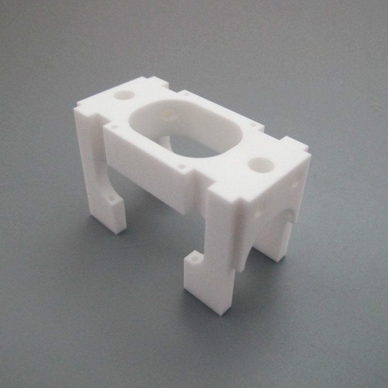
Complex pockets, holes and datum relationships require route-specific review.
Material grade
Purity, stabilization, supplier and fired state
Functional faces
Datums, sealing lands, insulation paths and wear surfaces
Acceptance plan
Critical dimensions, edge criteria, finish and records
Material First
The ceramic family and exact grade set the available process window.
Route Before Tolerance
Green, machinable or fully fired stock leads to different controls.
Edge Integrity
Corner design and handling criteria are planned around brittle behavior.
Inspection by Function
Datums and acceptance methods follow the part application and drawing.
Choose the ceramic around the job it must do
Technical ceramics are not interchangeable. Electrical behavior, thermal path, wear, fracture risk, stock form and final machining route should be reviewed together before a part is quoted.
Alumina
Al2O3A versatile starting point for electrical insulation, hardness and wear resistance across multiple purity levels.
Confirm purity, stock condition, surface needs and whether final features are made before or after firing.
Zirconia
ZrO2Often considered when toughness, wear behavior and a dense finished surface matter more than low cost.
Confirm stabilization system, grade, finished geometry and the amount of fired-state grinding required.
Aluminum Nitride
AlNReviewed for components that need electrical insulation together with a strong thermal path.
Confirm material documentation, handling requirements, flatness, hole geometry and finish before stock is ordered.
Silicon Nitride
Si3N4A candidate for demanding mechanical, thermal-shock and wear environments.
Fired material is difficult to machine, so near-net geometry and diamond finishing scope must be agreed early.
Silicon Carbide
SiCConsidered where stiffness, hardness, dimensional stability and severe wear performance drive the design.
Define grade, surface condition, edge acceptance and only the truly functional precision features.
Machinable Glass Ceramic
MACOR TYPEUseful for prototypes and complex insulating parts that benefit from conventional machining without a firing step.
Confirm approved material brand or equivalent, wall thickness, thread strategy, finish and operating environment.
Material names above describe common review categories, not an automatic stock or performance guarantee. The customer should specify the approved grade and application requirements.
The same drawing can require three very different manufacturing plans
YXT reviews when the geometry is created, what dimensional change remains, which surfaces are functional and how brittle edges will be protected through inspection and packing.
Start with material state, not machine type.
A tolerance that is practical in machinable stock may demand diamond grinding after firing in another ceramic. The quotation should name the assumed state and finishing route.
Machinable Ceramic Stock
Suitable machinable glass ceramics can be milled, drilled and turned using conventional machining methods with material-specific parameters.
Control focus: wall support, edge breakout, thread form, surface finish and approved material.
Green-State Machining
Features are created before firing, with allowances planned around the ceramic body, supplier process and expected dimensional change.
Control focus: shrink model, datum strategy, near-net geometry and post-fire verification.
Fired-State Diamond Finishing
Fully fired technical ceramics may need diamond grinding, lapping or polishing for final functional faces and dimensions.
Control focus: stock allowance, heat, chipping, edge condition, finish and inspection access.
Protect the part before chasing a smaller tolerance
Ceramic components reward clear load paths, supported edges and deliberate datums. Early design review can remove avoidable grinding, reduce chipping risk and make inspection more meaningful.
Ceramics prefer compression and supported geometry.
Prefer broad contact and controlled clamping.
Avoid sharp contacts and unsupported thin sections.
Final suitability remains the product designer's responsibility. YXT reviews manufacturability from the supplied drawing and application notes.
Corners and radii
Use practical internal radii and remove sharp transitions where tool access or stress concentration creates unnecessary risk.
Edges and thin walls
Add edge breaks where function allows and identify any edge that must remain sharp for sealing, optics or assembly.
Holes and depth
Through-holes and supported drilling paths are generally easier to control than deep blind microfeatures.
Threads and inserts
State the assembly load and consider inserts, larger thread forms or alternate retention where direct ceramic threads are fragile.
Datums and flat faces
Define the functional datum structure, mating faces and only the flatness or parallelism needed by the assembly.
Different materials leave different machining fingerprints
These examples show the range of geometry that can be reviewed. Exact material, finish, dimensional capability and production route remain drawing-specific.
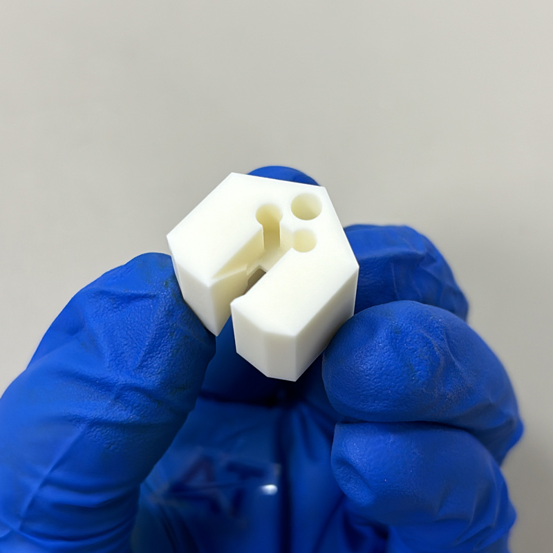
Insulating Clamp Geometry
Slots, holes and supported outer faces reviewed around edge integrity and approved grade.
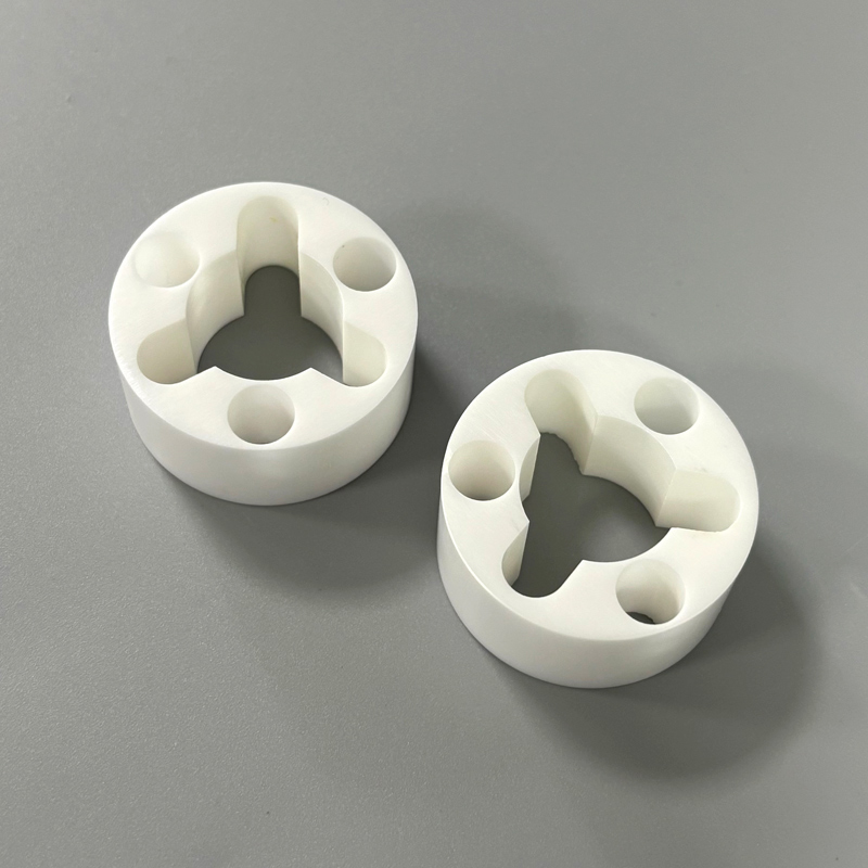
Wear-Resistant Ring Components
Circular parts with repeated holes and internal profiles where fired-state finishing may control final fit.
Multi-Face Structural Component
A complex body with pockets, through-features and multiple datums that requires route planning before tolerance review.
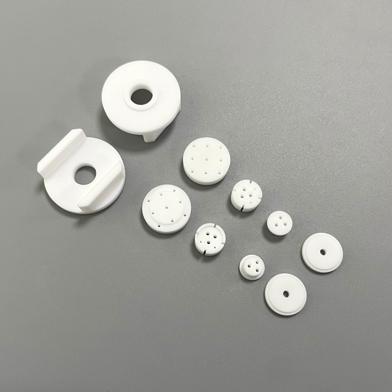
Small Precision Insulators
Prototype-scale discs and insulating details suited to careful conventional machining when the material is approved.
Make every callout answer a manufacturing question
A useful ceramic drawing distinguishes functional faces, fit dimensions, edge acceptance and cosmetic expectations. YXT aligns the proposed inspection method with the agreed feature and record scope.
01
Size and position
Datum system, limits and fit relationship
Route and workholding protect the critical relationship
Suitable dimensional instruments or CMM strategy
02
Flatness and parallelism
Functional faces and measurement basis
Stock allowance and finishing sequence are planned together
Surface plate, indicator, optical or CMM method as agreed
03
Surface condition
Required finish, polished zone or sealing function
Cut, grind, lap or polish scope is identified in the quote
Comparator, profilometer or agreed visual standard
04
Edges and chips
Critical edges, allowed break and unacceptable defects
Handling, deburring and packing follow the edge priority
Magnification and agreed visual acceptance criteria
05
Material identity
Exact grade, purity, supplier or approved equivalent
Stock and documents are confirmed before production
Supplier records or order-specific documentation when agreed
Measurement method, report format, sampling and record retention should be requested during RFQ. They are included only after written confirmation.
Use ceramic where the material solves a real system problem
The strongest RFQ explains the environment and failure mode, not only the part shape. That context helps YXT review grade, route, geometry and inspection together.
Electrical and High Voltage
Insulators, spacers, stand-offs and feedthrough-related hardware where electrical separation and dimensional stability matter.
Define voltage environment, creepage path, mating hardware and cleanliness.
Semiconductor and Vacuum Tooling
Fixtures, nests, guides and precision support parts used around controlled process and handling systems.
Define vacuum, particle, outgassing, flatness and cleaning requirements.
Wear, Flow and Chemical Service
Guides, seats, nozzles, bushings and interfaces selected around abrasion, media exposure and long-term geometry.
Define fluid, temperature, contact load, wear pair and leakage criteria.
Thermal and Optical Assemblies
Insulating supports, thermal-path parts and stable mounting features used with sensors, optics and electronics.
Define thermal path, expansion interface, surface function and assembly preload.
A five-gate path from drawing to packed ceramic parts
Each gate closes a different risk: material identity, manufacturing route, brittle geometry, inspection method and handling.
Application Brief
Receive CAD, drawing, quantity, service environment, mating parts and critical characteristics.
Grade and State
Confirm the exact ceramic, stock form, supplier documentation and green, machinable or fired state.
DFM and Route
Review radii, walls, holes, datums, edge risk, workholding and the proposed finishing sequence.
Controlled Build
Machine with route-specific tooling, handling and in-process checks around the approved revision.
Inspect and Protect
Verify the agreed characteristics, clean as specified and pack to protect brittle edges in transit.
Lead time begins after drawings, material, quantity, route and documentation scope are confirmed.
Questions to settle before a ceramic drawing is released
The answers below are general planning guidance. Final capability depends on the exact grade, material state, geometry, quantity, finish and inspection scope.
Which ceramic materials can YXT review?
Common review categories include alumina, zirconia, aluminum nitride, silicon nitride, silicon carbide and machinable glass ceramic. Availability, exact grade, documentation and processing route are confirmed for each RFQ.
Can fired ceramic be CNC machined like aluminum?
Usually not. Fully fired technical ceramics are hard and brittle, so final features may require diamond grinding, lapping or polishing. Machinable glass ceramic and green ceramic bodies follow different routes. The material state must be known before capability is assessed.
What tolerance can YXT hold on ceramic parts?
There is no useful universal tolerance for every ceramic feature. Achievable limits depend on grade, fired state, size, geometry, stock allowance, finishing route, edge condition and measurement method. YXT reviews the drawing feature by feature.
How should I specify edge chips and corner breaks?
Identify functional edges, sealing edges and cosmetic zones, then state the allowed break or visual acceptance method. Where function permits, practical chamfers or radii help reduce damage during machining, inspection, assembly and shipping.
Can YXT make prototypes and repeat ceramic parts?
YXT can review prototypes, pilot quantities and repeat orders. The appropriate route depends on material state, stock availability, tooling, inspection and whether the geometry is likely to change after early testing.
What files should I send for a ceramic quotation?
Send a 3D model and controlled 2D drawing together with material grade, quantity, application, critical datums, surface and edge requirements, inspection records, cleaning needs and any approved supplier restrictions.
Send the drawing before the ceramic route is locked.
YXT will review the grade, geometry, critical faces, expected quantity and inspection scope, then respond with the assumptions that control manufacturability and quotation.
3D CAD and controlled 2D drawing
Exact ceramic grade and material state
Quantity, revision and delivery target
Critical dimensions, edges and surfaces
Inspection, cleaning and document scope