
Custom Shaft Machining & Manufacturing
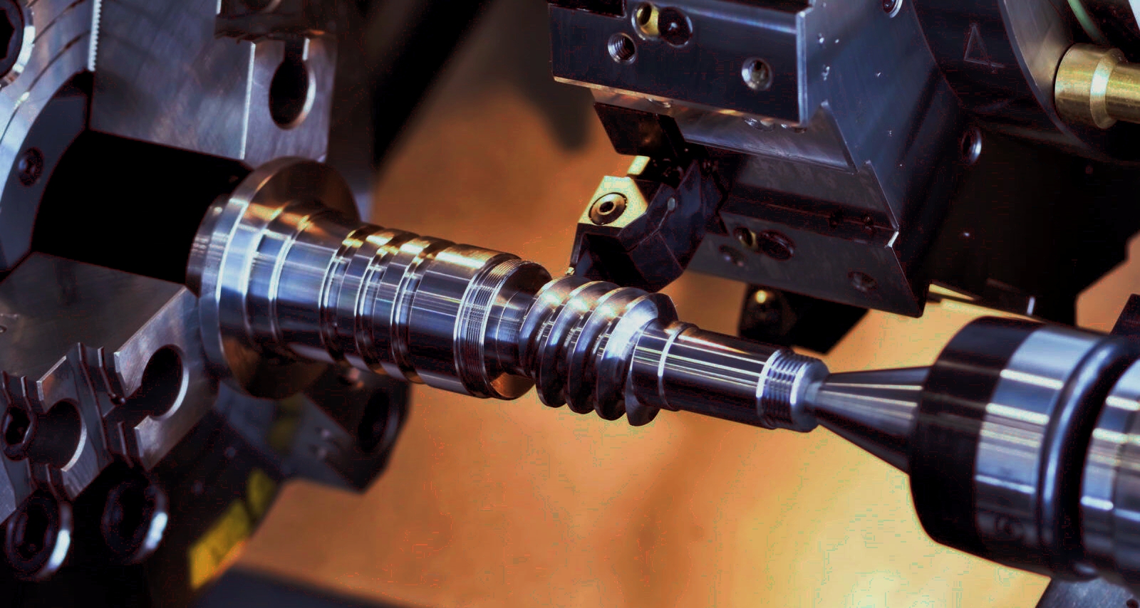
YXT manufactures stepped, keyed, splined, hollow and precision shafts from drawing review through CNC turning, milling, grinding, heat treatment, finishing and inspection.
Final tolerance, runout, roughness and lead time are confirmed from material, geometry, datum scheme, quantity and inspection requirements.
+/- 0.005 mm
Drawing-dependent dimensional tolerance review
Ra 0.4 um
Grinding or polishing target where geometry allows
100+ Options
Metals, plastics, heat treatments and finishes
Prototype to Production
Quantity and manufacturing route reviewed per project
What is custom shaft manufacturing?
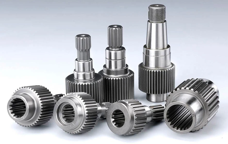
A custom shaft is more than a turned cylinder. Its shoulders, journals, bores, threads, keyways, splines and surface condition must work together with bearings, seals, gears and couplings. We plan the machining sequence around the functional datums and critical-to-quality features on your drawing.
Datum strategy, concentricity, runout and bearing-seat relationships
Feature access for threads, flats, keyways, splines and cross holes
Material condition, heat-treatment allowance and finish sequence
Inspection method matched to the dimensions that control assembly
How YXT machines customized shafts
The route is selected around geometry, tolerance, material condition and production quantity. Several processes may be combined to protect datum relationships and final surface requirements.
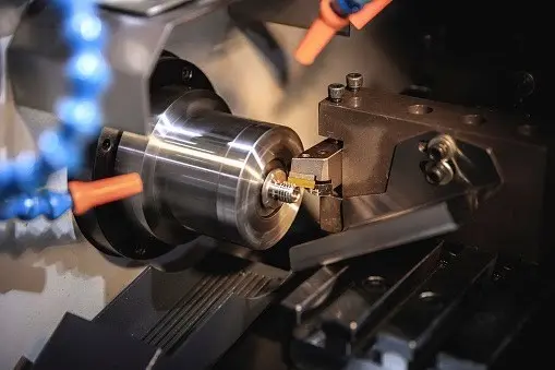
CNC Turning
Forms the main diameters, shoulders, grooves, tapers, threads and bores while controlling the shaft axis.
View Related Capability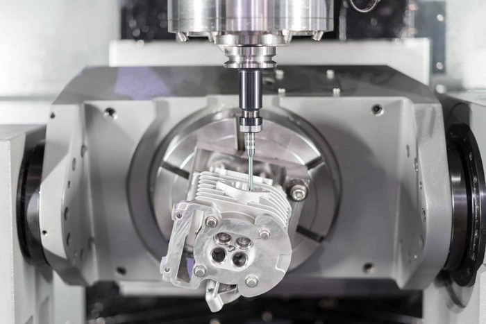
CNC Milling
Adds keyways, flats, slots, cross holes, bolt patterns and complex end features with indexed or multi-axis setups.
View Related Capability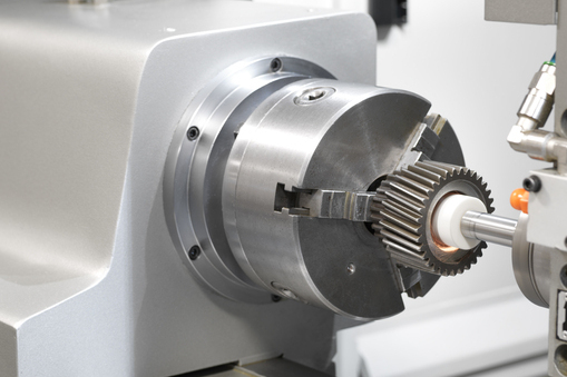
CNC Grinding
Refines bearing seats, seal surfaces and critical diameters after rough machining or heat treatment when tighter finish is required.
View Related Capability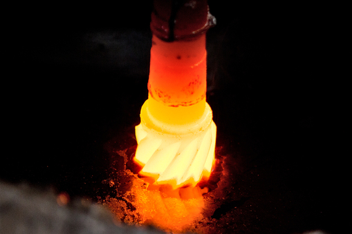
Heat Treatment
Carburizing, hardening, tempering or stress-relief routes are reviewed against material, hardness depth, distortion and grinding allowance.
View Related Capability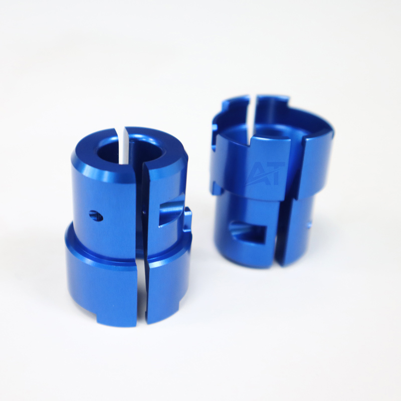
Surface Finishing
Plating, anodizing, passivation, black oxide, polishing and other finishes are coordinated with masking and tolerance requirements.
View Related CapabilityCustom shaft machining capabilities
Use these values as project-planning references. YXT confirms the production route and inspection plan after reviewing your model, dimensioned drawing, material, quantity and application.
Capability
Project planning reference
Shaft size
Small and medium precision shafts; diameter and length are reviewed against machine travel, slenderness and workholding.
Dimensional tolerance
Down to +/- 0.005 mm on suitable features when material, geometry, process sequence and inspection support it.
Runout and concentricity
Confirmed from the functional datum scheme, feature spacing, length-to-diameter ratio and specified inspection method.
Surface roughness
As-machined, ground or polished surfaces; targets down to Ra 0.4 um may be evaluated for suitable journals and seal surfaces.
Machined features
Steps, shoulders, tapers, external and internal threads, keyways, flats, cross holes, bores, grooves and splines.
Production quantity
Prototype, bridge and repeat-production quantities are planned around setup, inspection, tooling and material availability.
Inspection options
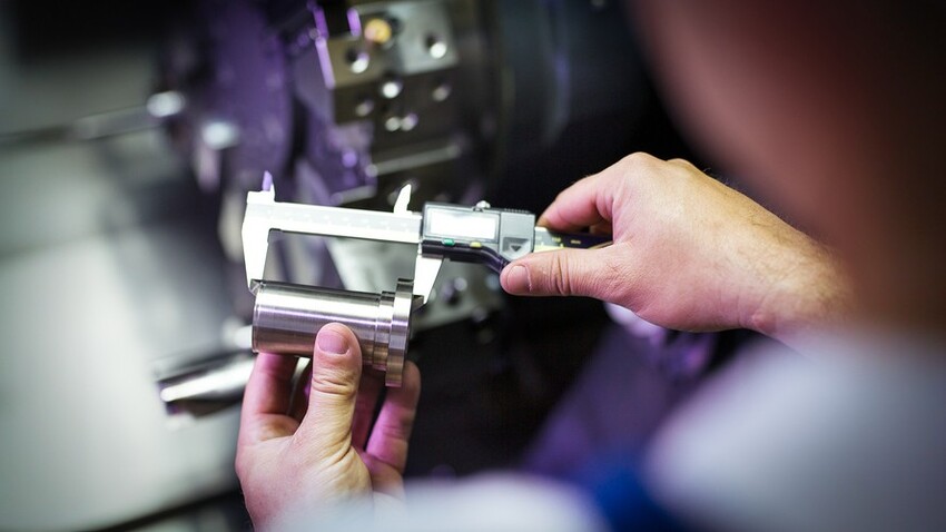
Micrometer, bore gauge, height gauge, surface-roughness checks, runout fixtures and CMM where feature access is suitable.
Capability values are not blanket guarantees. Final acceptance criteria must be stated on the released drawing and confirmed during quotation.
Match the material to load, wear and environment
Strength is only one variable. Shaft material selection should also consider fatigue, corrosion, temperature, weight, machinability, hardness response, bearing contact and the required finish.
Ask About Material OptionsCarbon & Alloy Steel
High strength, fatigue resistance and heat-treatment flexibility for loaded transmission and drive components.
Common grades: 1045, 4140, 4340, 8620
Stainless Steel
Corrosion resistance and cleanability for food equipment, medical hardware, marine systems and general machinery.
Common grades: 303, 304, 316, 17-4PH
Aluminum Alloy
Low mass, good machinability and corrosion resistance for automation, instruments and lightweight assemblies.
Common grades: 6061, 6082, 7075
Brass & Copper
Useful for electrical, thermal, low-friction and corrosion-sensitive applications with moderate mechanical loads.
Common grades: C360, C464, C110
Titanium Alloy
High specific strength and corrosion resistance for aerospace, medical and demanding lightweight mechanisms.
Common grades: Grade 2, Grade 5
Engineering Plastics
Low weight, electrical insulation and low-friction behavior for sleeves, rollers and lightly loaded shafts.
Common grades: POM, PA, PEEK, PTFE
Common types of custom shafts
The same project may combine several forms. YXT reviews transitions, tool access, datum relationships and inspection access before defining the machining sequence.
Solid Shafts
A straightforward load-carrying form used for motors, rollers, transmissions and general mechanical assemblies.
Hollow Shafts
Reduces mass or allows wiring, fluid or another component to pass through the center while preserving useful stiffness.
Stepped Shafts
Uses multiple diameters and shoulders to locate bearings, gears, seals, spacers and retaining features.
Tapered Shafts
Provides controlled seating, alignment or self-locking behavior for hubs, tooling and rotating assemblies.
Splined Shafts
Transfers torque through multiple teeth while supporting axial engagement, accurate indexing or sliding motion.
Keyed Shafts
Uses milled keyways, flats or drive features to connect gears, couplings, pulleys and timing components.
Custom shafts and precision turned components
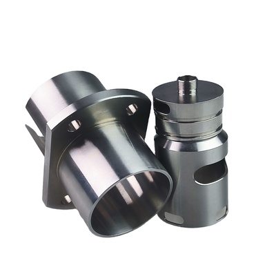
Representative parts show the variety of materials, diameters and secondary features YXT can review. Submit your drawing for project-specific manufacturability feedback.
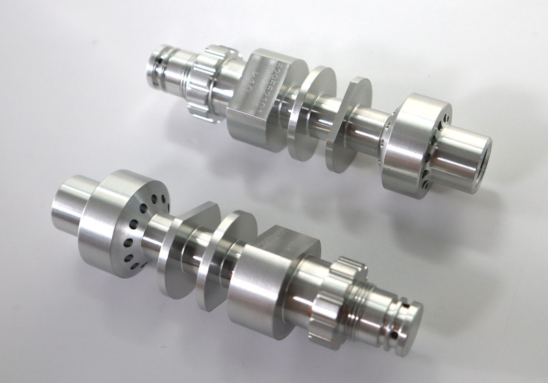
Aluminum Stepped Shafts
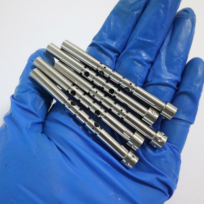
Stainless Precision Shafts
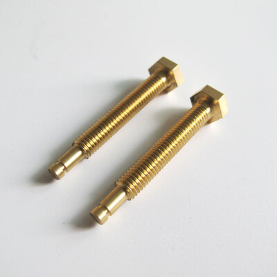
Brass Turned Components
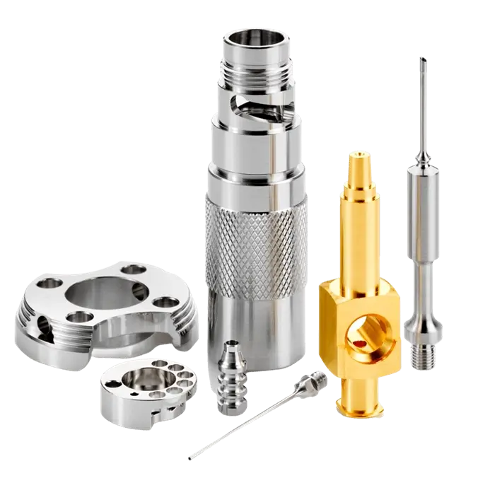
Production Turned Parts
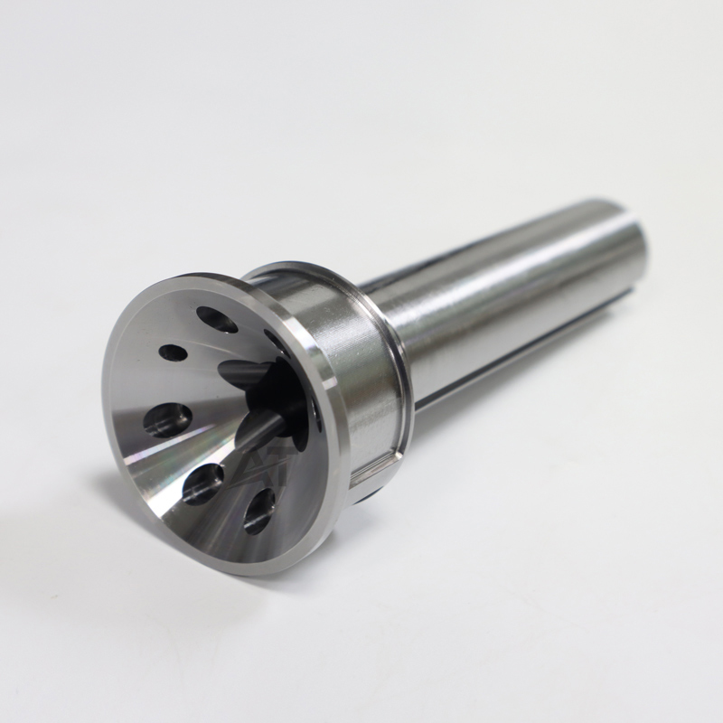
Steel Drive Components
Titanium Turned Parts
Eight practical tips for custom shaft design
Clear functional priorities reduce setup risk, inspection ambiguity and unnecessary cost. These checks help the drawing communicate what the assembly truly needs.
Define load and speed. State torque, bending, impact, fatigue and rotational speed so material and heat treatment can be reviewed.
Control slenderness. Long small-diameter shafts may need steady support, alternate stock or revised tolerances to manage deflection.
Use practical shoulders. Add suitable fillets and reliefs where bearings, gears and seals meet changes in diameter.
Plan drive features. Dimension keyways, splines, flats and cross holes from functional datums and show fit requirements.
Prioritize critical tolerances. Apply tight limits to assembly-driving features instead of every diameter and length.
Coordinate heat treatment. Allow for distortion, stock removal, hardness depth and post-treatment grinding where needed.
Specify roughness by function. Bearing journals, seal surfaces and cosmetic zones do not need the same finish.
Make inspection possible. Define accessible datums and state how runout, concentricity or position should be measured.
Inspection follows the shaft datum strategy
A diameter can be in size while the assembly still fails from runout or datum mismatch. YXT reviews the drawing, process sequence and inspection method together so measurements reflect how the shaft functions.
Drawing & CTQ Review
Identify functional datums, fits, runout, roughness, hardness and documentation requirements before production.
First-Piece Verification
Confirm setup, tool path and critical dimensions before the production quantity continues.
In-Process Checks
Monitor diameters, lengths and runout at appropriate manufacturing stages, including after heat treatment when relevant.
Final Release
Complete the agreed dimensional, surface and documentation checks before protective packing and shipment.
Process Coordination
Turning, milling, grinding, heat treatment and finishing planned as one route.
DFM Feedback
Drawing questions are raised before they become production or inspection problems.
Flexible Quantities
Prototype and repeat-production routes are reviewed around the real project volume.
Clear Communication
Quotation assumptions, critical risks and requested documentation are confirmed in writing.
Questions about custom shaft manufacturing
Send the latest drawing and quantity for advice tied to your actual geometry, material and assembly requirements.
Ask YXT an Engineering QuestionWhich processes are used to make custom shafts?
Most shafts begin with CNC turning. Milling adds keyways, flats, slots and cross holes; grinding refines critical journals; heat treatment changes strength or wear behavior; and finishing provides corrosion protection, appearance or surface performance. The exact route depends on the drawing.
What materials are recommended for precision shafts?
Common choices include carbon steel, alloy steel, stainless steel, aluminum, brass, titanium and engineering plastics. Select the grade from load, fatigue, corrosion, temperature, weight, hardness, friction and finishing requirements rather than machinability alone.
How tight can shaft tolerances and runout be?
Suitable features may be reviewed down to +/- 0.005 mm, while runout and concentricity depend on datum definition, shaft length, wall thickness, heat treatment, setup sequence and inspection method. YXT confirms achievable values after drawing review.
Can YXT machine splines, keyways and cross holes?
Yes. These secondary features can be evaluated through indexed turning, CNC milling, broaching or suitable partner processes. Provide the spline standard, key size, angular relationship, fit and inspection requirements on the drawing.
Can YXT support prototypes and repeat production?
Yes. We review prototypes, bridge quantities and repeat production. The tooling, workholding, inspection frequency and unit economics are planned around quantity, geometry stability and expected future demand.
What information is needed for an accurate quotation?
Provide a 3D model, dimensioned 2D drawing, material and condition, quantity, finish, heat treatment, critical-to-quality features, inspection or documentation needs, delivery destination and target schedule. Note the shaft application when it affects load, speed or mating fits.
Ready to review your custom shaft project?
Send YXT your CAD files, dimensioned drawing and project requirements. We will review the machining route, critical features, material, finish, inspection scope and quotation assumptions.
INCLUDE WITH YOUR RFQ
3D CAD and dimensioned 2D drawing
Material, condition and heat treatment
Quantity now and expected repeat volume
Finish, CTQ features and inspection needs