
UAV Servo Components Manufacturing
YXT manufactures precision housings, gear-train parts, output shafts, splines, mounting hardware and optional mechanical subassemblies for industrial and commercial UAV servo programs. Send the drawing, material, quantity and critical fit requirements for a route review.
Machined housings and covers
Gears, shafts and bearing interfaces
Optional mechanical subassembly
Electrical motors, PCBs, firmware, communication protocols and flight certification are outside the default scope unless separately reviewed and quoted.
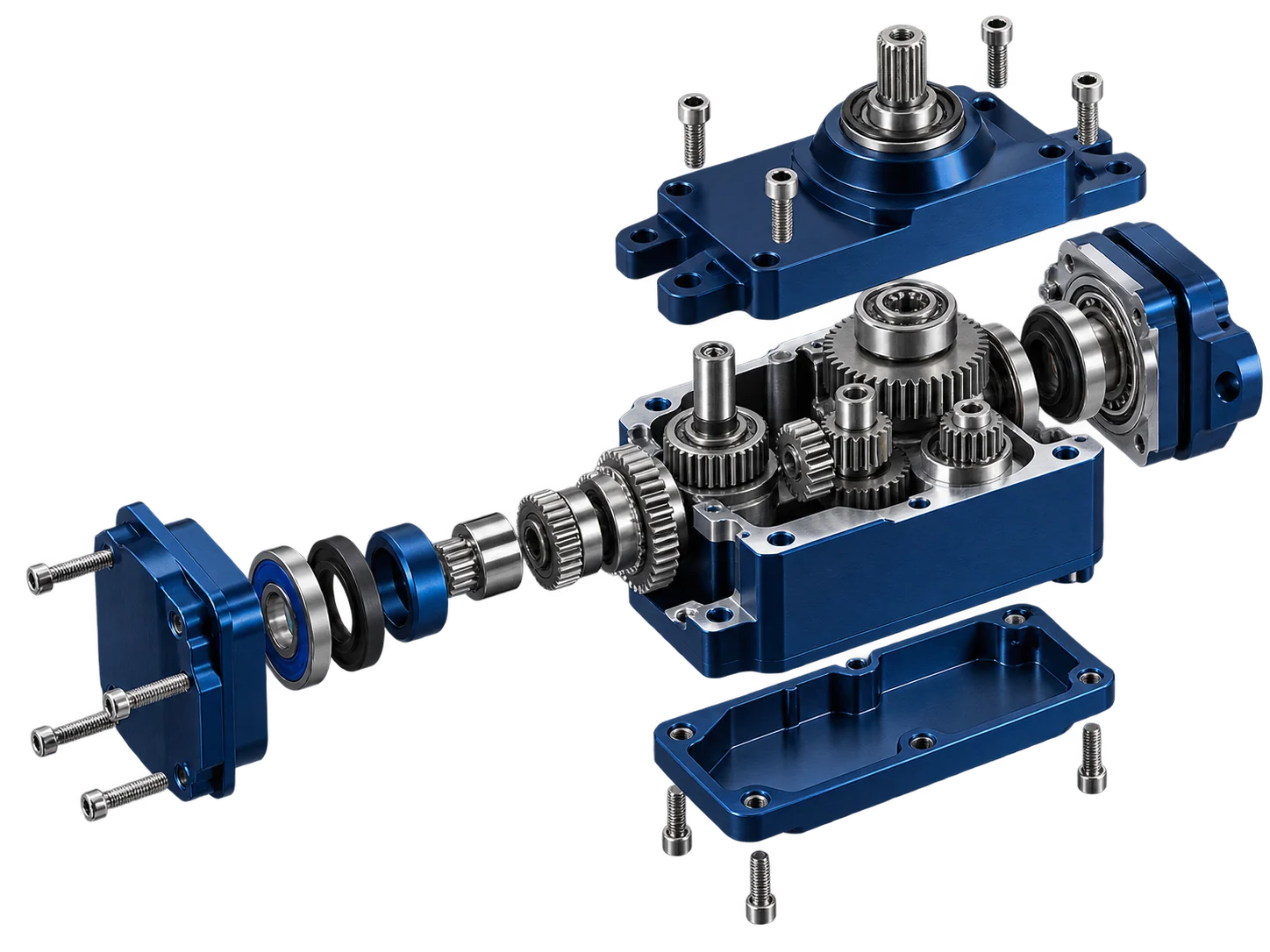
Housing, gear train, bearings, output spline and mounting interfaces shown for engineering context.
2D drawing + 3D model
Fits, datums + gear relationships
Parts or mechanical subassembly
Drawing-Driven DFM
Geometry, tolerance, material and assembly requirements are reviewed before the process route is released.
Prototype to Repeat Runs
Support can begin with fit-check parts and continue into controlled repeat production.
Mechanical Subassemblies
Bearing press-fit, pins, shafts and gear-train loading can be quoted when acceptance criteria are defined.
Critical Feature Inspection
Inspection planning follows the functional datums, bearing seats, splines and mating interfaces on the drawing.
Inside the UAV Servo Mechanical Stack
A compact servo concentrates multiple fit and motion relationships into a small envelope. YXT reviews the housing, rotating parts and mounting datum as one mechanical chain.
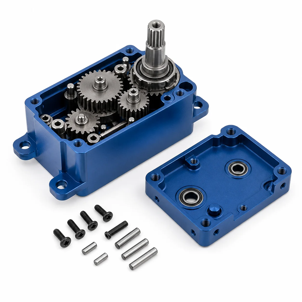
Conceptual mechanical arrangement for DFM discussion. Final geometry, gear relationship and stack-up follow the customer-controlled design.
Housing & Covers
Machined shells establish bearing positions, cover interfaces, mounting geometry and the protected mechanical envelope.
Gear Train
Pinions, gears, pins and spacers convert motion while center distance, tooth geometry and axial stack influence running clearance.
Output Shaft & Spline
The output interface carries the external linkage and is reviewed around spline profile, runout, shoulder location and load path.
Bearing Seats & Pins
Bores, dowels and shaft journals control alignment. Fit classes and functional datums should be explicit on the drawing.
Mounting Interface
Flanges, brackets and threaded features locate the mechanism in the airframe or payload structure and transfer external load.
Mechanical Components Built from Your Controlled Drawings
The part family can be quoted as individual components or as a coordinated mechanical package. Each route is selected after geometry, material, quantity and acceptance criteria are reviewed.
Machined Housings & Covers
Lightweight aluminum enclosures with bearing pockets, ribs, bosses, sealing lands, threaded holes and mounting references.
Typical inputs: alloy, finish, datum system, bearing fits and cover interface.
Gears, Pinions & Gear Pins
Small steel or copper-alloy motion parts reviewed around tooth definition, center distance, shaft relation and post-process condition.
Typical inputs: gear data, material, hardness, tooth quality and mating gear information.
Output Shafts & Splines
Turned, milled and ground output members with shoulders, grooves, spline or keyed interfaces and controlled runout.
Typical inputs: profile standard, fit, datum axis, heat treatment and surface requirements.
Control Horns & Linkages
Compact arms, horns, clevis-related hardware and connecting features produced for the defined motion and mounting geometry.
Typical inputs: load direction, interface geometry, material, finish and edge condition.
Bearing Seats, Sleeves & Spacers
Precision bores, journals, bushings, sleeves and axial spacers used to establish rotation, alignment and stack height.
Typical inputs: bearing specification, fit class, mating part, lubrication and measurement method.
Mounting Brackets & Structural Interfaces
Machined brackets and attachment features that connect the servo mechanism to the airframe, gimbal or industrial payload.
Typical inputs: interface drawing, mass target, fasteners, datum scheme and finish.
Control the mechanical chain, not just each isolated dimension.
Compact servo mechanics depend on how bores, shafts, gears, covers and mounting datums relate after finishing and assembly. YXT plans the route around the drawing-defined function.
Capability statements are typical planning guidance. Final limits and inspection methods are confirmed feature by feature after drawing review.
Backlash & Center Distance
Gear mesh behavior is influenced by tooth geometry, shaft location, center distance, axial stack and the mating component condition.
Planning: review gear definition and datum chain. Verification: drawing-defined feature and functional checks.
Bearing Bore Position
Bearing pockets must locate rotating members relative to the housing datums and opposing cover without introducing unwanted misalignment.
Planning: bore sequence and finishing allowance. Verification: size, position and datum relationship.
Coaxiality & Runout
Shaft shoulders, journals, splines and output features are planned around a functional rotational axis rather than independent diameters.
Planning: common setup or controlled transfer. Verification: drawing-defined runout and profile checks.
Weight vs. Stiffness
Pockets, ribs and thin walls must balance mass reduction with machining stability, bearing support and fastener load transfer.
Planning: stock, workholding and cutting sequence. Verification: wall, mass or geometry requirements when specified.
Cover Flatness & Sealing Lands
Mating faces and sealing lands are reviewed for finish allowance, burr control, cover clamp behavior and post-finish dimensional change.
Planning: protect functional faces and define masking. Verification: flatness, surface and mating condition.
Assembly Datum Chain
Pins, bearings, spacers, gears and covers create a cumulative stack that should be controlled from a deliberate assembly reference.
Planning: identify key characteristics. Verification: part inspection plus agreed mechanical fit-up checks.
Select the Material Around Load, Wear, Mass and Environment
YXT combines in-house machining with managed specialist processes where the drawing calls for gear generation, heat treatment, grinding or surface finishing.
01
6061 / 7075 Aluminum
Housings, covers, horns and lightweight brackets
3/5-axis milling, precision boring and thread control
Anodizing or conversion coating as specified
02
17-4PH / Stainless Steel
Output shafts, pins, splines and corrosion-resistant hardware
Turning, milling, grinding and profile control
Passivation or project-specific heat treatment
03
4140 / 4340 Alloy Steel
Loaded gears, pinions and high-strength shafts
Turning, gear cutting, grinding and controlled deburring
Heat treatment and protective finish per drawing
04
Brass / Bronze
Bushings, wear interfaces and small precision inserts
Turning, boring, reaming and controlled deburring
As-machined or specified treatment
05
POM / PEEK & Engineering Plastics
Spacers, isolators and selected low-load interfaces
CNC machining with burr and distortion control
As-machined unless otherwise specified
Exact grade, stock source, heat treatment, coating, inspection records and specialist process route are confirmed after drawing review. Managed external processes are identified in the quotation when applicable.
Servo Mechanical Components on a Consistent Product Canvas
These images illustrate the mechanical categories YXT can review. Production geometry, material, finish and inspection follow the customer-controlled drawing.
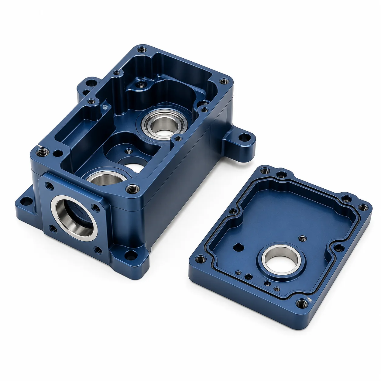
Machined Housing & Cover
Bearing pockets, mounting bosses, threaded interfaces and cover lands in a compact aluminum package.
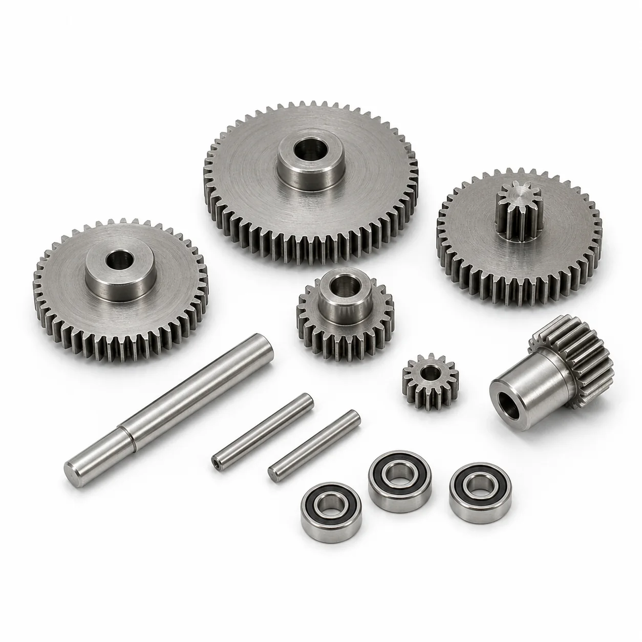
Miniature Gear Train Parts
Pinions, gears, shafts and spacers reviewed as a coordinated center-distance and stack-height system.
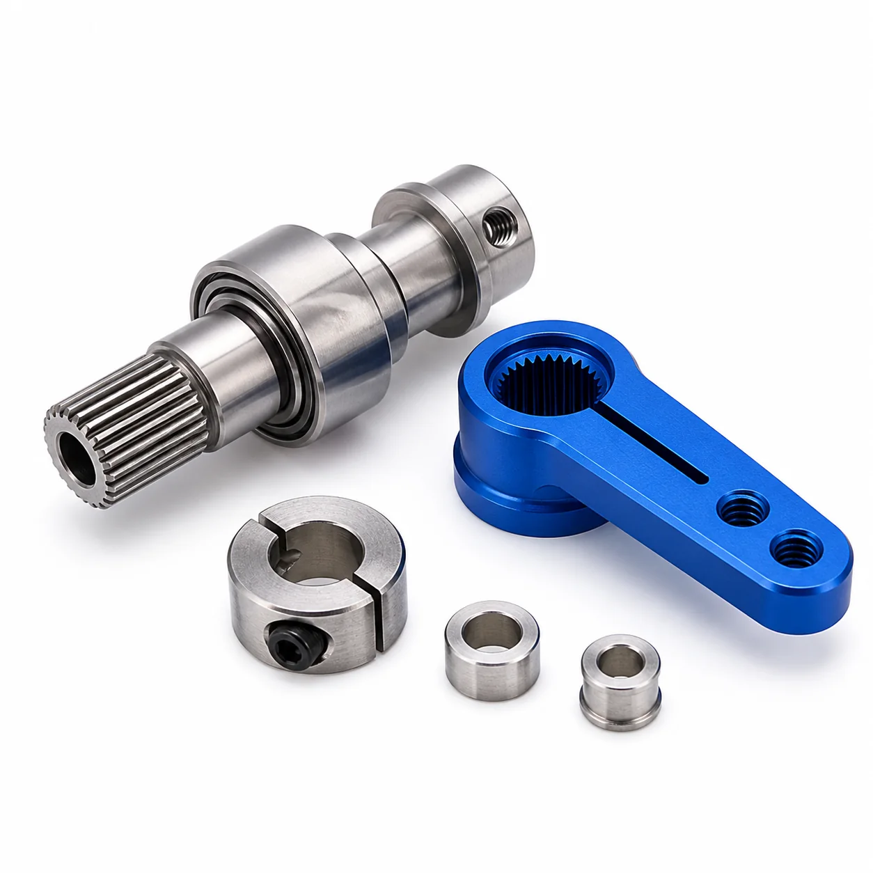
Output Shaft & Control Horn
Turned and milled output interfaces with shoulders, spline geometry, fastening features and controlled rotational datum.
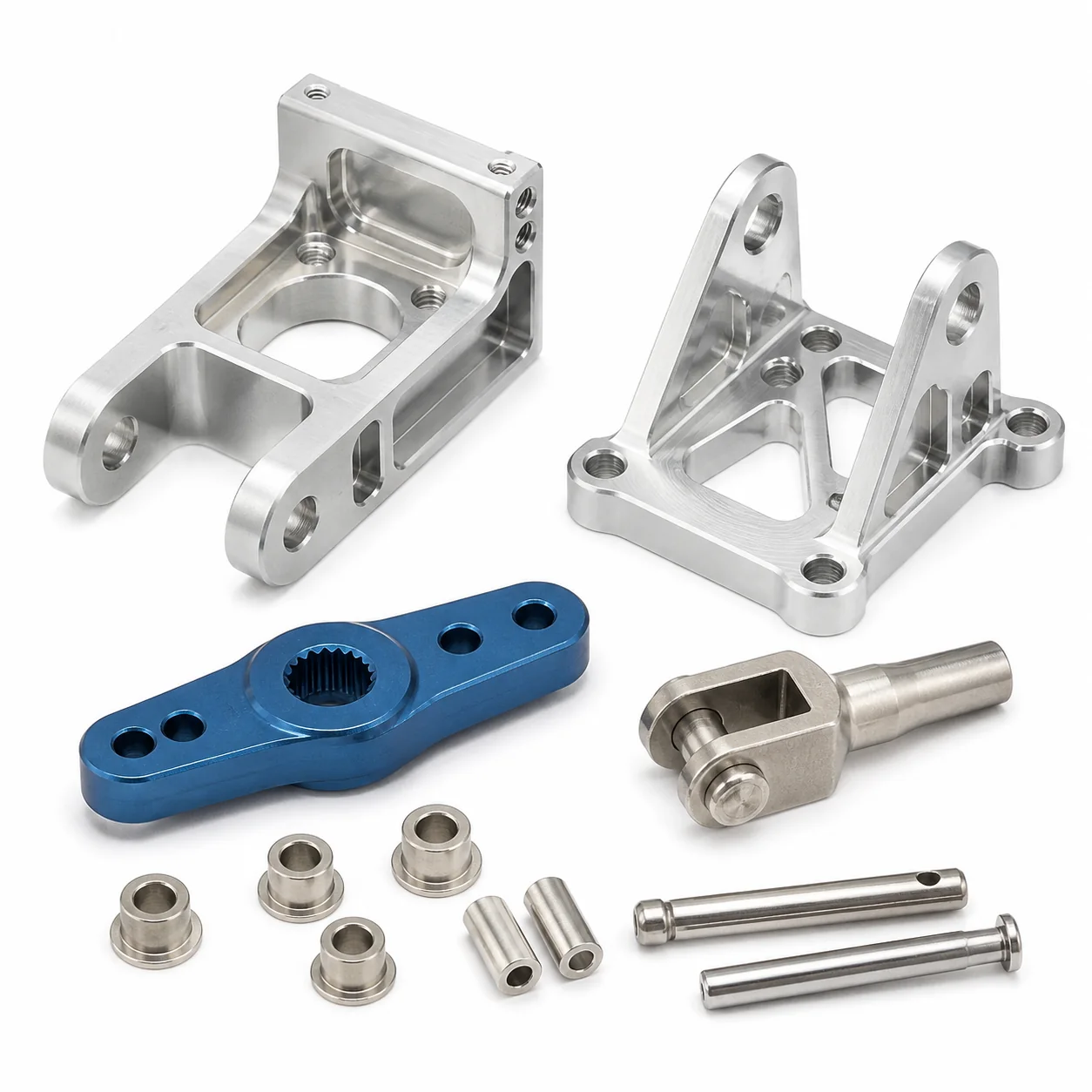
Mounting & Linkage Hardware
Lightweight brackets, horns and connecting hardware for airframe, payload or mechanism interfaces.
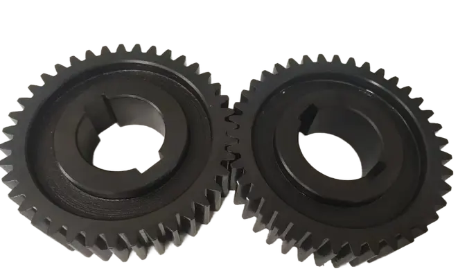
Heat-Treated Steel Gears
High-strength gear components can be routed through drawing-specified heat treatment and final feature control.
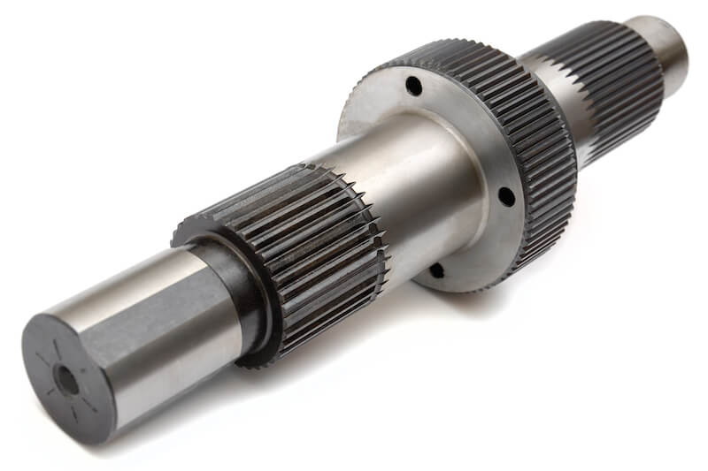
Precision Splined Shaft
Output and transmission shafts produced around the functional axis, profile, fit, shoulder and runout requirements.
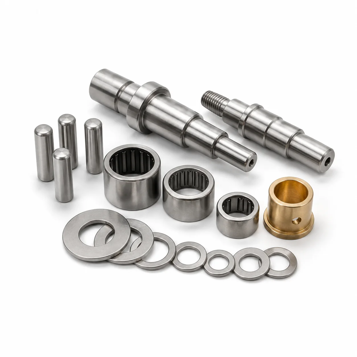
Bearing, Pin & Spacer Hardware
Ground pins, stepped shafts, bearing sleeves, spacers and bushings planned around the assembly fit and datum chain.
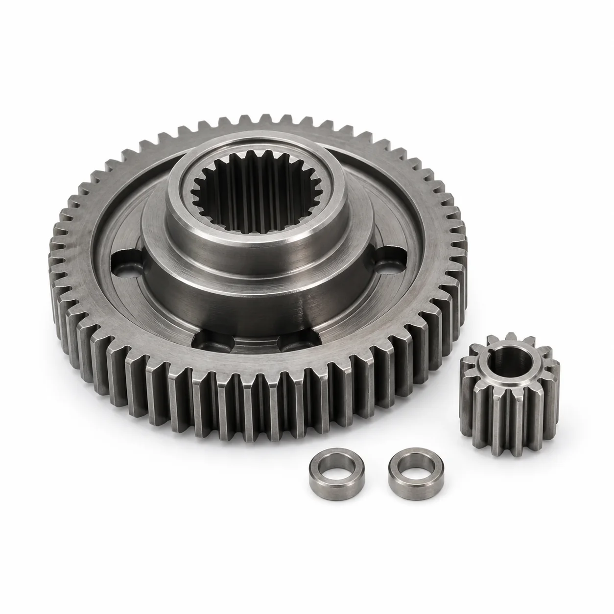
Output Gear & Pinion Pair
Coordinated gear and pinion features reviewed for center distance, spline fit, stack height and controlled running clearance.
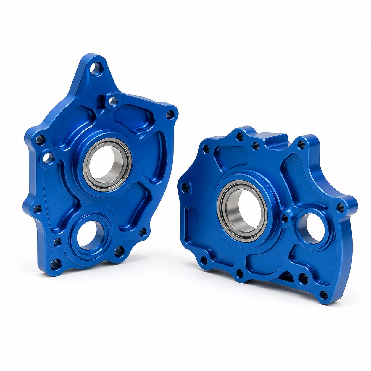
Lightweight Servo Side Plates
Pocketed aluminum plates combine low mass with bearing support, mounting definition and post-anodize interface control.
Mechanical Subassembly When the Acceptance Plan Is Defined
YXT can quote selected mechanical fit-up work when the customer supplies an assembly drawing, component status, lubricant or handling requirements and measurable acceptance criteria.
Bearing & Pin Fit: press, slip or retained fits are performed to the drawing-defined condition.
Gear Train Loading: approved gears, shafts, pins and spacers are loaded in the specified sequence.
Free Rotation & Backlash Check: agreed mechanical movement or clearance checks are recorded when defined.
Mechanical Record & Packing: accepted subassemblies are identified and protected for the next production stage.
Default scope boundary
Motors, control boards, sensors, firmware, communication protocols, environmental qualification and flight certification are not included by default. Customer-supplied components or expanded testing can be reviewed as a separate requirement.
Mechanical Motion Components for Industrial and Commercial UAV Platforms
The platform context helps identify load direction, weight targets, environmental exposure, maintenance access and the mechanical acceptance plan.

Fixed-Wing Control Surfaces
Mechanical parts for compact control-surface actuation packages where output geometry, mounting stiffness and low free play matter.
Application image for context; not a customer claim.
VTOL Tilt & Link Mechanisms
Housings, shafts, brackets and linkage hardware for drawing-defined tilt or transition mechanisms in industrial VTOL platforms.
Feasibility and acceptance criteria are confirmed against the customer drawing.
Gimbal & Payload Positioning
Precision shafts, bearing interfaces, brackets and compact gear components used around camera, sensor or payload positioning mechanics.
Feasibility and acceptance criteria are confirmed against the customer drawing.

Industrial Multirotor Mechanisms
Lightweight mechanical parts for payload, inspection and utility UAV systems with repeatable mounting and service interfaces.
Application image for context; not a customer claim.
Link Every Critical Characteristic to the Mechanical Function
The inspection plan follows the released drawing and agreed records. Functional relationships are reviewed before individual dimensions are assigned to a measurement route.
Feature-to-Method Planning
Bearing seats
Bore size, position and relationship to the functional datum system.
Output spline / shaft
Profile, diameter, shoulder location, runout and drawing-defined fit.
Gear features
Tooth or profile characteristics and agreed drawing-defined checks.
Cover & sealing lands
Flatness, surface condition, edge control and mating geometry.
Mechanical subassembly
Agreed fit, free motion, backlash or record requirements when included.
Drawing-to-Delivery Gates
RFQ Package Review
Receive the 3D model, controlled 2D drawing, quantity, material and assembly context.
DFM & Route Definition
Confirm the datum chain, key features, manufacturing sequence and managed specialist processes.
First Components
Produce the agreed prototype, first article or initial quantity against the released revision.
Feature Inspection
Verify the agreed characteristics with the defined method and record level.
Optional Fit-Up
Complete approved bearing, pin, shaft or gear-train mechanical work when included in scope.
Packed Release
Identify, protect and release accepted parts or subassemblies for delivery.
Questions Before a UAV Servo Mechanical Package Is Released
These answers describe YXT mechanical manufacturing scope. Final capability, process and acceptance criteria are confirmed against the actual drawing package.
Does YXT supply a complete flight-ready UAV servo?
Not as the default offer. YXT focuses on precision mechanical components and optional mechanical subassemblies. Motors, electronics, firmware, communication protocols, environmental qualification and flight certification require separate capabilities and are not implied by this page.
Which UAV servo components can YXT manufacture?
Typical review categories include machined housings and covers, gears and pinions, gear pins, bearing sleeves and spacers, output shafts and splines, control horns, linkage hardware and mounting brackets. Feasibility depends on geometry, material, quantity and drawing requirements.
How is gear backlash controlled?
Backlash is not controlled by one dimension alone. The review considers gear definition, center distance, shaft and bearing location, axial stack, housing datums and the condition of mating parts. The drawing should define the required method or functional acceptance criteria.
Which materials are available?
Common candidates include 6061 and 7075 aluminum, 17-4PH and other stainless steels, 4140 or 4340 alloy steel, brass, bronze and suitable engineering plastics such as POM or PEEK. The exact grade and condition are confirmed for each RFQ.
Can YXT coordinate heat treatment and surface finishing?
Yes, drawing-specified heat treatment, anodizing, passivation, plating, conversion coating and selected gear or grinding processes can be coordinated through a managed route. The quotation identifies applicable external specialist processes and documentation scope.
Can I order prototypes before repeat production?
Yes. YXT can review prototype and fit-check quantities before repeat production. The route may change as geometry stabilizes, so revision control and the purpose of each build should be included with the RFQ.
What files and specifications should I send?
Send the 3D CAD model and controlled 2D drawing together with quantity, exact material, heat treatment, finish, gear data, bearing specification, critical fits and datums, mating-part information, inspection records and any requested mechanical subassembly scope.
Send the Servo Mechanical Package for Review
YXT will review the part family, functional datum chain, material, quantity, finish and optional mechanical fit-up scope, then return the manufacturing assumptions that control quotation.
2D drawing and 3D CAD
Material, heat treatment and finish
Critical fits, datums and gear relationships
Quantity and mechanical assembly scope