
Precision Components, Engineered by Function
YXT turns controlled drawings into machined, formed and finished components. Start with the interface, motion, load and surface requirements; we map the manufacturing route around the part.
Tolerance, surface finish, documentation and lead time are confirmed against the released drawing, material, geometry and quantity.

+/- 0.005 mm
Drawing-dependent tolerance review for suitable features
100+ Materials
Metals, engineering polymers and project-specific stock
Prototype to Production
Route planning matched to quantity and revision status
One Coordinated Route
Machining, forming, finishing and inspection planning
A component atlas, not a catalog
Begin with what the part must locate, transmit, seal, support or present. The geometry and acceptance requirements then determine the process route.
Six geometries, six different manufacturing questions
The examples below organize parts by engineering behavior instead of industry labels, making it easier to identify the route and controls that matter.
Housings & Manifolds
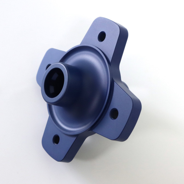
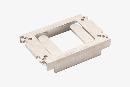
Coordinate ports, sealing lands, precision bores and mounting datums so connected components assemble from one controlled reference system.
Shafts & Rotational Parts
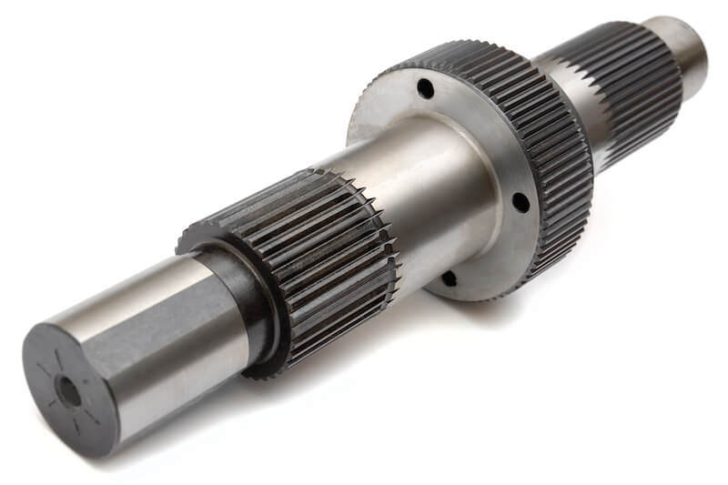
Plan diameters, shoulders, splines, keyways and bearing fits around common axis control, runout and functional transitions.
Brackets & Structural Parts
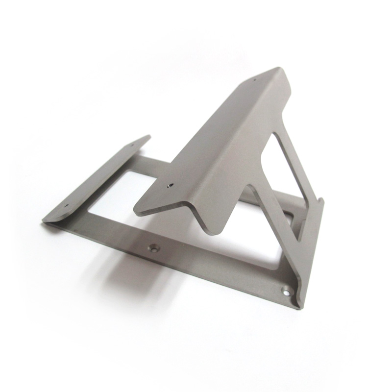
Balance stiffness, weight, mounting relationships and tool access for structural parts that position larger assemblies.
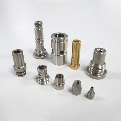
Miniature & Swiss Components
Control small diameters, dense features, threads and burr-sensitive edges where handling and measurement access become part of the process.
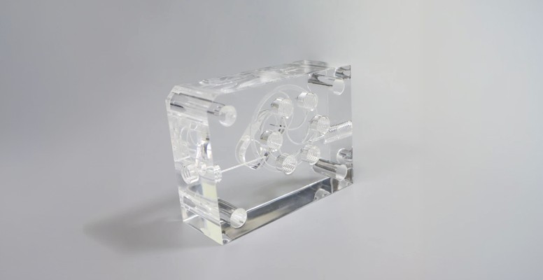
Plastic & Fluidic Parts
Select stock, cutting strategy and clamping around stability, chemical exposure, friction, optical needs and sealing interfaces.
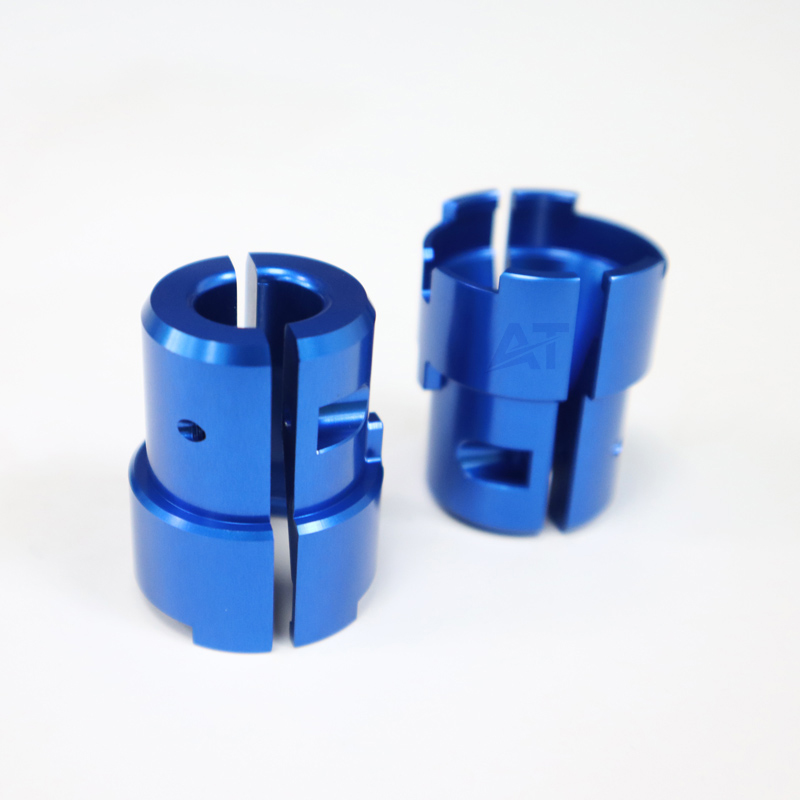
Cosmetic & Finished Parts
Connect machining allowances, masking zones, edge condition and appearance criteria before anodizing, plating, coating or heat treatment.
Geometry chooses the route
A quote becomes useful when the manufacturing route reflects the dominant geometry and the features that actually control function.
Critical dimensions should be identified on the 2D drawing. YXT then reviews datum transfer, setup count, finishing allowance and inspection access before confirming capability.
#
Dominant geometry
Likely route
Critical controls
01
Axis-led geometry
CNC turning, live tooling and grinding
Concentricity / runout / thread fit
02
Multi-face geometry
3-, 4- and 5-axis CNC milling
Datum transfer / true position / flatness
03
Small, dense features
Swiss and micro machining
Burr control / edge integrity / measurement access
04
Thin-wall profiles
Laser cutting, bending and forming
Bend allowance / distortion / assembly fit
05
Performance surfaces
Anodizing, plating, coating or heat treatment
Masking / buildup / appearance / post-finish size
Tolerance is a system, not a badge
A tight number is only meaningful when datums, process sequence, finish allowance and measurement method all describe the same functional intent.
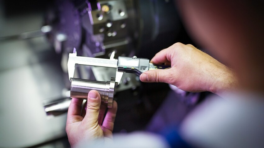
Functional datum
Locate the interfaces that drive assembly, motion or sealing before assigning secondary dimensions.
Process sequence
Plan roughing, stabilization, finishing and secondary operations around material movement and setup transfer.
Surface allowance
Account for anodizing, plating, coating, heat treatment, grinding or polishing before releasing the machining route.
Inspection strategy
Match gauges, CMM access, surface checks and reporting scope to the drawing and actual acceptance decision.
The released drawing remains the acceptance authority. Capability is confirmed feature by feature after material, geometry, quantity and inspection requirements are reviewed.
Different parts demand different controls
Use these examples to identify the closest geometry, then send the controlled drawing so the actual route can be reviewed around your requirements.
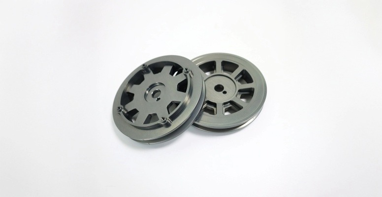
Aluminum machined components
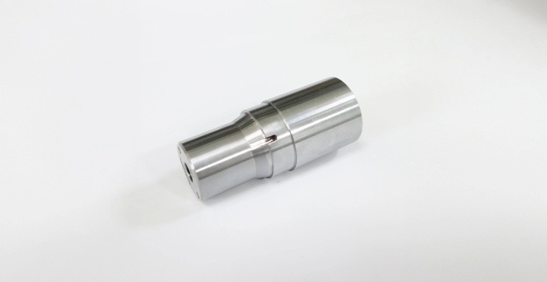
Stainless steel components
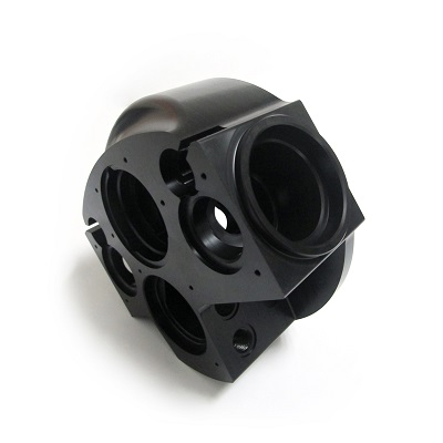
POM functional components
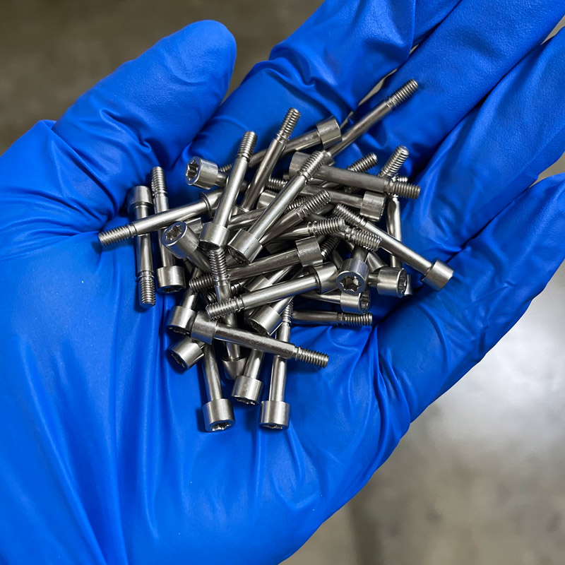
Swiss-machined components
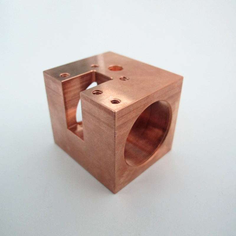
Copper precision components
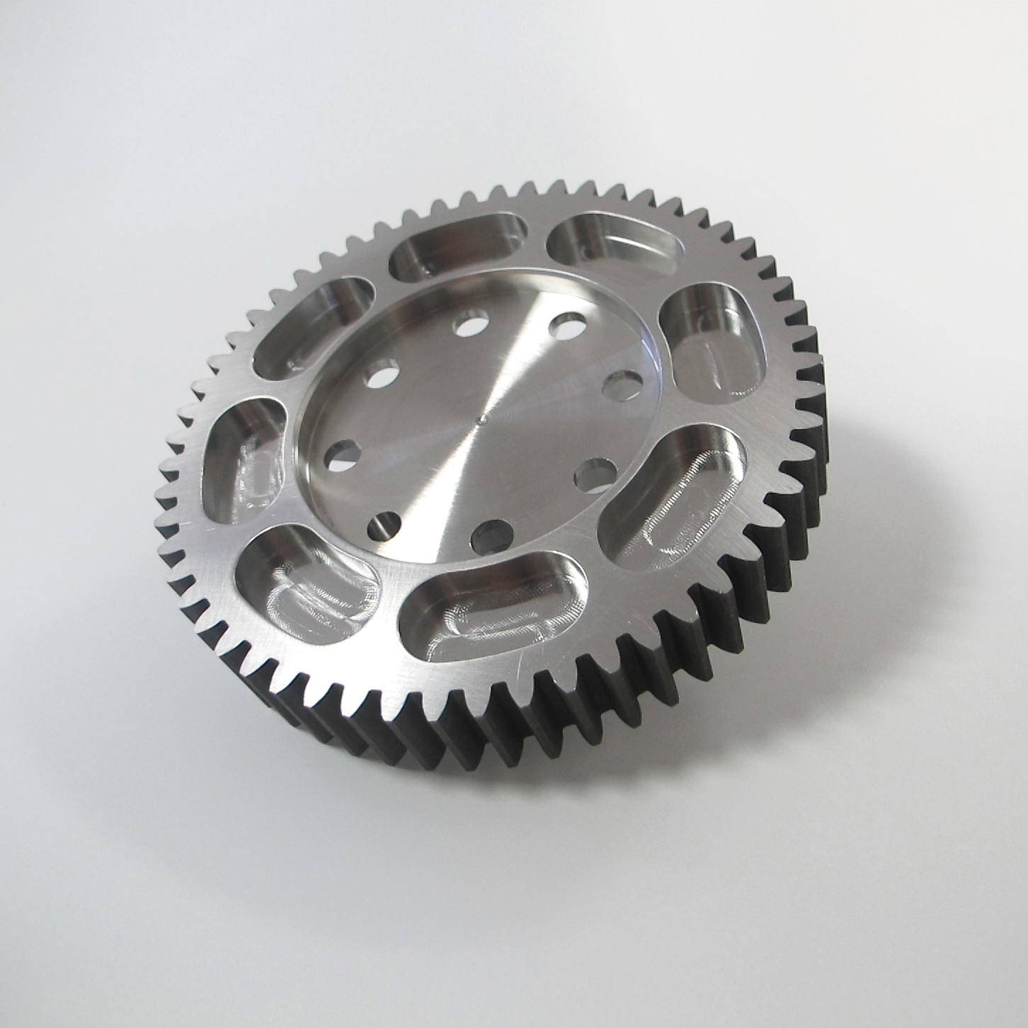
Inspection-ready features
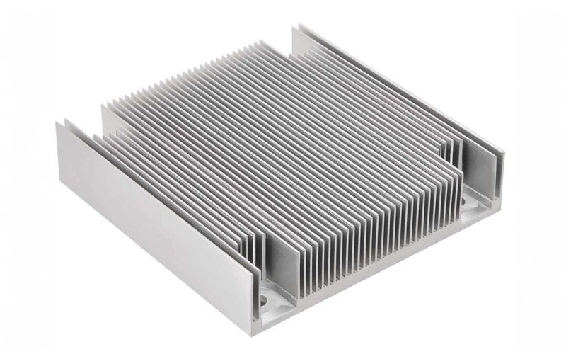
Thermal management components
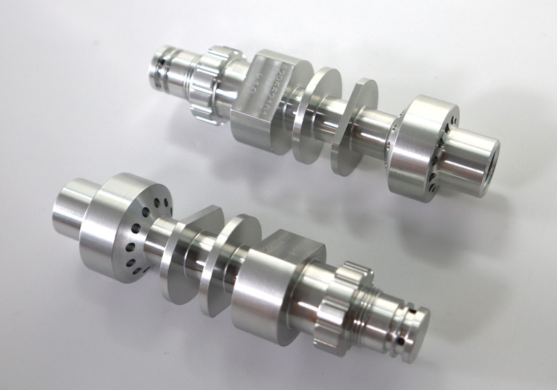
Aluminum stepped shafts
From drawing to validated component
Each checkpoint has a different purpose: clarify intent, choose the route, verify the first output, control repetition and release the finished lot.
Drawing intake
Review CAD, controlled 2D drawing, material, quantity, finish and documentation requirements.
Route review
Map setups, datums, tooling, secondary operations, inspection access and manufacturability risks.
First-piece verification
Check critical features before the remaining quantity proceeds under the confirmed process route.
Controlled production
Maintain revision, workholding, tool condition and in-process checks appropriate to the project.
Final release
Complete agreed dimensional, visual, surface and documentation checks before packing and shipment.
Lead time is quoted from the confirmed drawing, material availability, quantity, process complexity, finishing and inspection scope.
Ready to review your component?
Send YXT the latest CAD, controlled drawing and project requirements. We will review the dominant geometry, datums, material, finish, quantity and inspection scope before quotation.
INCLUDE WITH YOUR RFQ
Controlled 2D drawing and current 3D CAD
Material, finish and masking requirements
Critical dimensions, datums and inspection scope
Prototype, pilot and expected production quantities