
Kovar Alloy CNC Machining
Drawing-led CNC turning, milling, drilling and sealing-interface machining for reviewed ASTM F15 and UNS K94610 Kovar components.
Send the material specification, product form and condition, 3D model, controlled drawing, sealing surfaces, quantity, finishing route and documentation scope.
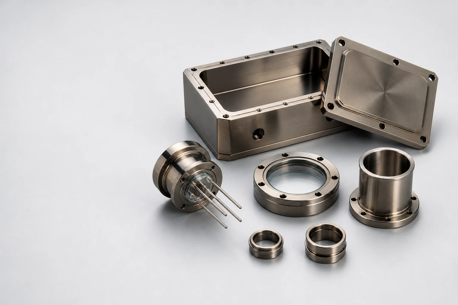
ASTM F15 Review
Grade, product form, temper and supplied condition checked before quotation
Sealing Interfaces
Lands, bores, edges and cleanliness zones reviewed as functional features
Prototype to Repeat
Revision-controlled engineering quantities and repeat production batches
Feature-Led QA
Datums, thin walls, pin holes, threads, sealing faces and quoted records

Control Heat Before It Becomes Geometry
Kovar can smear, work harden and move when the setup, cutting edge or heat path is unstable. The route is planned around the final sealing feature, not only removal rate.
Keep the Setup Short and Rigid
Stable workholding and low overhang help protect concentric bores, thin flanges and sealing lands from chatter and movement.
Cut Cleanly Without Dwell
Sharp tooling and continuous engagement reduce rubbing, smearing and repeated contact with a work-hardened surface.
Manage Coolant and Chip Flow
Coolant delivery, chemistry and chip evacuation are selected around the application and any downstream sealing or cleaning requirement.
Finish the Functional Edge Deliberately
Deburring and edge control are planned so sealing lands, glass interfaces, pin holes and plating allowances remain intact.
Machining Routes for Hermetic and Precision Hardware
Each route starts with the functional interface, material condition, thermal history and inspection state shown on the controlled drawing.
Turned Rings, Collars and Pins
Concentric diameters, sealing collars, feedthrough bodies, sleeves, pin features and retaining rings with controlled edge condition.
Milled Packages and Lids
Electronic package frames, covers, cavities, flange patterns and datum-controlled sealing lands machined from reviewed stock.
Thin-Wall Housings and Flanges
Sensor bodies, optical housings, windows and vacuum hardware with staged stock removal and support around flexible features.
Micro Holes, Threads and Ports
Small bores, pin arrays, vent paths, threaded features and side ports reviewed for depth, access, burr direction and gaging.
Managed Post-Machining Operations
Selected cleaning, annealing, oxidation, plating, grinding or joining support can be coordinated when explicitly included in the approved quotation.
Treat Kovar as a Controlled-Expansion System
ASTM F15 and UNS K94610 identify an iron-nickel-cobalt alloy whose chemistry and thermal expansion are controlled for glass and ceramic sealing applications. Product form, condition and thermal history still matter to the part route.
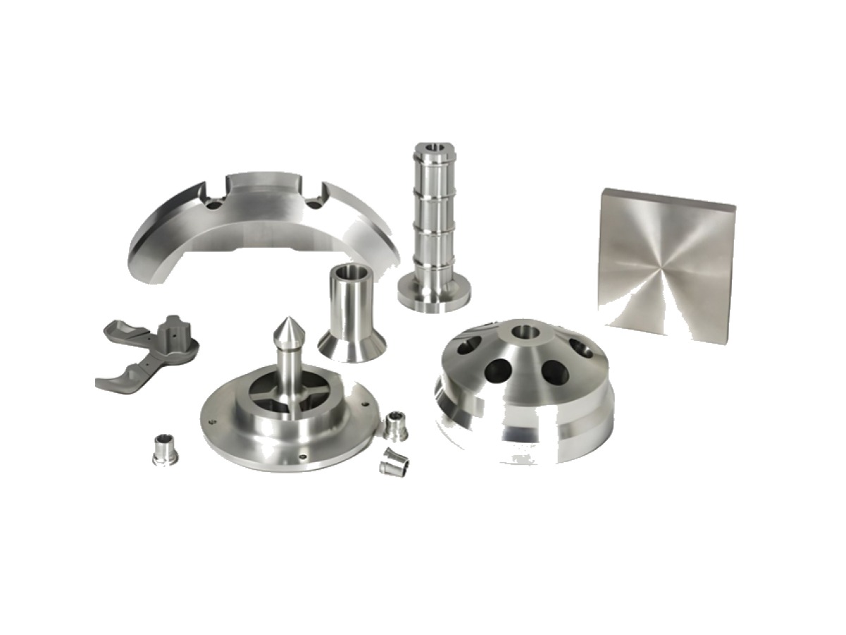
ASTM F15 / UNS K94610
Controlled-expansion Fe-Ni-Co alloy
Use the governing specification and approved drawing designation. Trade names alone should not replace the material requirement.
Nominal Chemistry
Iron balance, about 29% nickel and 17% cobalt
Chemistry is tightly controlled because it influences the expansion behavior used in compatible sealing systems.
Product Form and Condition
Bar, plate, tube, sheet or customer-supplied stock
State the supplied temper, annealed condition, stock route, surface scale and any cleanup allowance before quotation.
Sealing Surface State
Geometry, finish, edge and cleanliness
Identify the exact land or bore that interfaces with glass, ceramic, braze, weld or plating, including protected zones.
Thermal History
Stress relief, anneal, oxide or joining cycle
Show which dimensions apply before and after any thermal operation and who controls the approved heat route.
Finish and Protection
Bare, oxidized, plated or project-specific
Define plating allowance, masking, contact surfaces, cosmetic limits and packaging protection on the RFQ.
Material and property notes support manufacturability review only. Final seal design, expansion match, thermal cycle and end-use qualification remain controlled by the customer drawing and assembly process.
Translate Kovar Risk into Inspectable Controls
The exact route changes with stock condition, wall thickness, sealing system, quantity and downstream thermal processing.
Heat-Induced Movement
Use a stable setup, balanced stock removal, controlled heat input and an inspection state that matches the drawing requirement.
Flatness, runout, profile or agreed fixture-state results after the specified process stage.
Smearing and Work Hardening
Maintain sharp tools, positive cutting and continuous engagement so finishing passes do not rub across a damaged surface.
Consistent surface condition and dimensional trend on critical bores and sealing lands.
Burrs at Pin Holes and Ports
Plan entry, exit, edge break and burr direction around glass interfaces, small bores and blind features.
Visual review, pin or bore gaging and drawing-compliant edge condition.
Thin-Wall Distortion
Stage roughing and finishing, support flexible geometry and define whether inspection is free, supported or restrained.
Wall map, concentricity, profile and post-release dimensional confirmation.
Contaminated Sealing Surface
Separate machining, deburring, cleaning and packaging requirements so oil, sulfur-bearing residue, loose abrasive or handling damage is controlled.
Quoted cleanliness, visual condition and protected packaging at release.
Define the Seal Before the Toolpath
A complete package separates dimensional machining requirements from the assembly, sealing and thermal assumptions controlled by the customer.
Material Specification and Product Form
State ASTM F15 or the approved equivalent, UNS designation, stock form, supplied condition and material certification requirement.
Glass, Ceramic or Joining Interface
Identify the functional sealing surface, compatible assembly material, interface diameter, land width, edge condition and protected area.
Critical Datums and Inspection State
Define datum relationships and whether flexible geometry is measured free, supported, restrained, before heat treatment or after finishing.
Thin Walls, Cavities and Cleanup
Show minimum wall zones, cavity floors, stock allowance, scale removal and any customer-controlled machining allowance.
Pin Holes, Threads and Small Ports
Call out hole depth, thread class, burr direction, break-through condition, gaging method and surfaces where edge break is restricted.
Thermal, Plating and Cleaning Sequence
Show which dimensions apply before or after annealing, oxidation, plating, brazing, welding or final cleaning, plus the required records.
Five Gates Before the Part Reaches Assembly
Material identity, roughing state, thermal sequence, final sealing features and release condition stay linked to the same controlled drawing.
Verify Material and Stock State
Confirm designation, lot, product form, condition, surface scale and machining allowance before the first setup.
Establish Datums and Rough Geometry
Create stable reference features and remove stock in a sequence that protects thin walls, cavities and concentric relationships.
Apply the Thermal or Stress Gate
When specified, pause at the approved state for stress relief, anneal or customer-controlled thermal processing before final dimensions.
Finish Sealing and Assembly Features
Complete lands, bores, pin holes, threads, ports and critical edges using the defined measurement state and finish allowance.
Clean, Inspect and Protect
Perform the quoted inspection and cleaning scope, preserve lot identity and package the functional surfaces against contact damage.
YXT does not infer a universal sealing cycle or leak-rate requirement. Assembly performance and qualification are reviewed only when separately specified and quoted.
Component Families Built Around Thermal Compatibility
Representative uses explain geometry and process needs. They do not identify YXT customers or claim qualification for a specific end system.
Hermetic Electronic Packages
Frames, cavities, lids and sealing perimeters for microelectronic or sensor packaging, machined to the controlled interface drawing.
Glass-to-Metal Feedthrough Hardware
Flanges, collars, pins, sleeves and small bores where concentricity, edge condition and surface state support a downstream sealing process.
Optical and Sensor Housings
Thin-wall bodies, windows, retainers, mounts and datum features used where thermal movement and alignment must be considered together.
Vacuum and Microwave-Tube Hardware
Rings, ports, packages and support components reviewed for sealing geometry, cleanliness, joining allowance and protected delivery.
Inspect the State That Will Enter the Next Process
Kovar parts can change through stress relief, annealing, oxidation, plating or joining. The quotation therefore identifies when each controlled feature is measured.
Records are quoted by project
Material certificates, lot traceability, first article, dimensional reports, plating or heat-treatment records and cleanliness requirements are included only when stated in the quotation.
Confirm Material Identity
Match the incoming lot, specification, product form and supplied condition to the approved RFQ and purchase requirement.
Verify Datums and Measurement State
Confirm support, alignment, temperature and pre-process or post-process inspection state for flexible or thermally sensitive geometry.
Release Sealing Features Early
Check critical lands, bores, pin holes, thin walls and edges before remaining stock value is committed.
Review Surface and Edge Condition
Inspect burrs, tool marks, scratches, contamination and protected zones according to the quoted visual and drawing requirements.
Complete Records and Protected Packing
Finish the quoted report, preserve lot identity and isolate sealing faces, pins, threads and thin walls from handling damage.
Representative Kovar Component Families
Original YXT page visuals show machining-focused part families on equal white canvases. Final geometry, thermal route and acceptance remain drawing-specific.
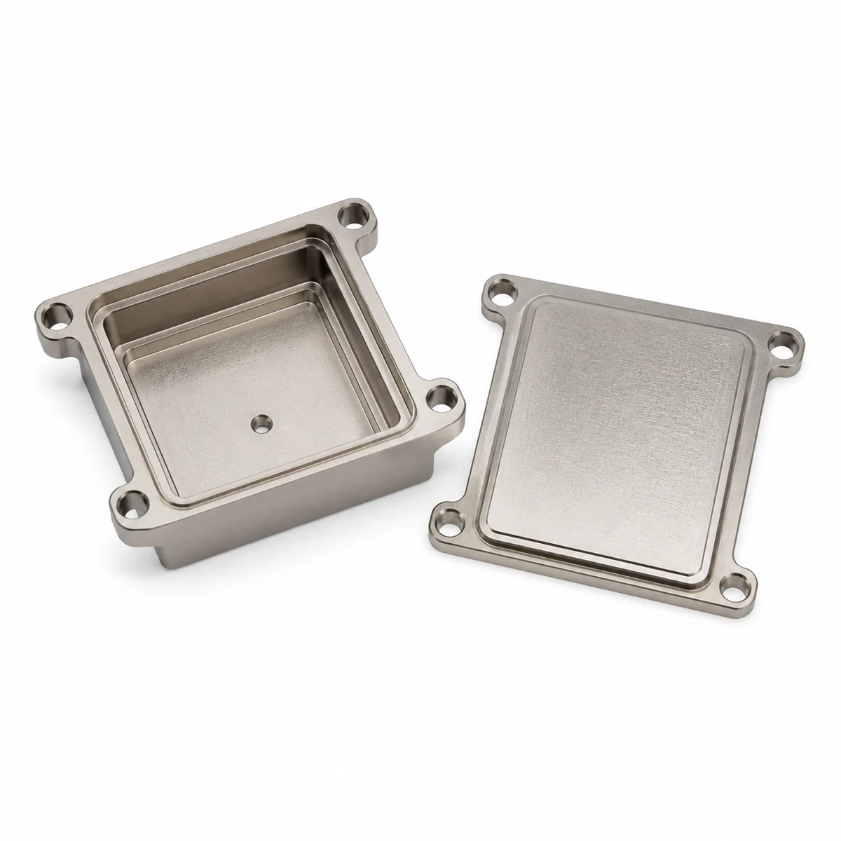
Package Housing and Lid
Cavity depth, sealing perimeter, flange pattern and datum faces machined for a reviewed assembly route.
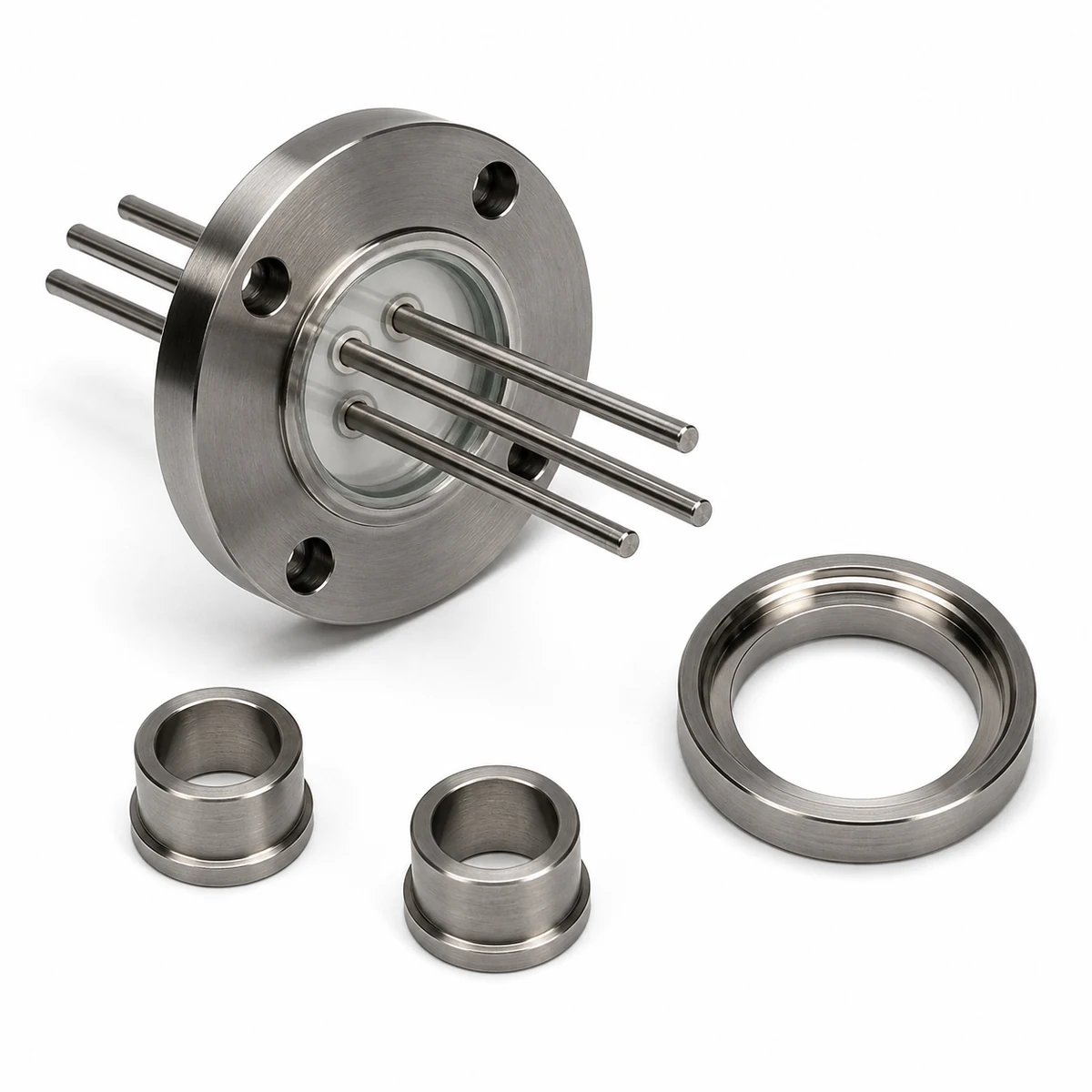
Feedthrough Components
Pin geometry, concentric bores, collars and sealing lands prepared for the specified downstream process.
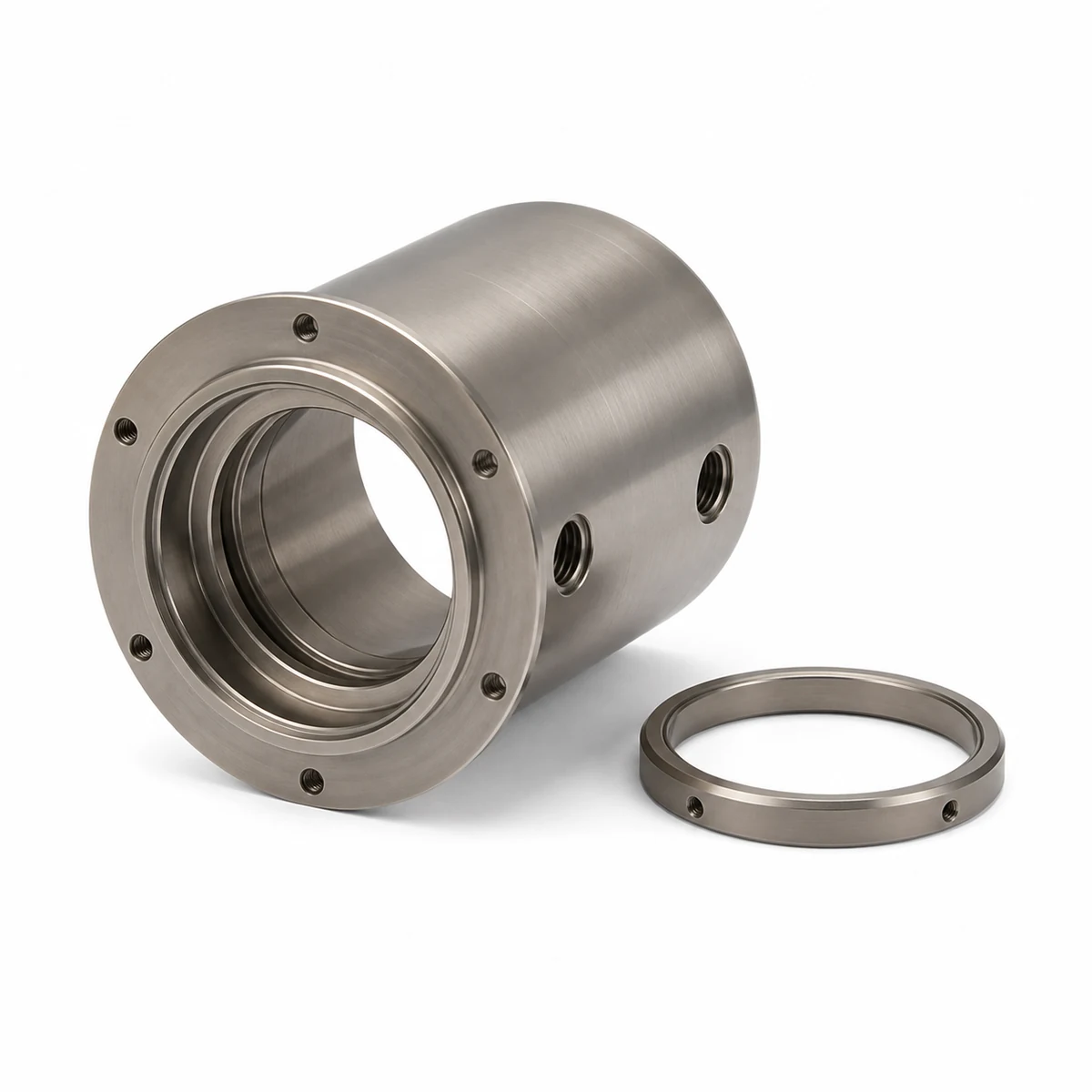
Optical Sensor Housing
Thin cylindrical wall, lens seat, ports and retaining features controlled around the drawing datum scheme.
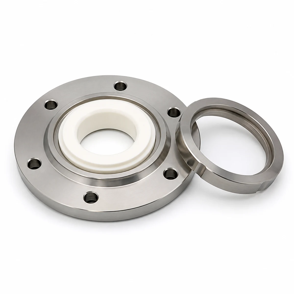
Ceramic Sealing Flange
Concentric flange, ceramic interface and retaining geometry shown as a representative machining family.
Kovar Alloy Machining FAQ
Final capability, process assumptions and inspection scope are confirmed against the exact specification, condition, geometry and sealing package.
What should I send for a Kovar machining quote?
Send the 3D model, controlled 2D drawing, ASTM F15 or approved material requirement, product form and condition, quantity, sealing interfaces, thermal and finishing sequence, critical datums, cleanliness scope and requested records.
Can YXT review ASTM F15 and UNS K94610 parts?
Yes. YXT can review Kovar parts identified to ASTM F15, UNS K94610 or a customer-approved equivalent. Acceptance depends on stock availability, supplied condition, geometry, quantity, finishing route and documentation scope.
Is Kovar the same material as Invar?
No. Both belong to the controlled-expansion alloy family, but they have different chemistry, expansion behavior and typical applications. The customer drawing should specify the exact required material.
Can YXT guarantee the hermetic leak rate of an assembled seal?
Machining can control the quoted geometry, surface and edge requirements, but assembled leak performance also depends on glass or ceramic selection, cleaning, oxide state, joining process, thermal cycle and test method. Leak testing is included only when separately reviewed and quoted.
Can you coordinate annealing, oxidation, cleaning or plating?
Selected secondary processes can be coordinated when they are explicitly included in the approved route and quotation. The customer should define the required sequence, masking, allowance, records and acceptance criteria.
What tolerance can YXT hold on Kovar parts?
No single tolerance applies to every Kovar component. Practical capability is reviewed against part size, wall thickness, feature access, stock condition, thermal sequence, plating allowance, quantity and measurement state.
Can YXT support prototypes and repeat production?
Yes. YXT can review one-off parts, engineering quantities and repeat batches. Material lot planning, revision control, fixtures, tool state, thermal routing, inspection scope and annual demand shape the production plan.
Send the Kovar Part Package for Review
YXT will review the material condition, sealing geometry, critical features, thermal sequence, quantity, finishing route and inspection scope before confirming the manufacturing assumptions for quotation.
3D CAD and controlled 2D drawing
ASTM F15 or approved material requirement
Sealing faces, thermal route and finish sequence
Quantity, cleanliness and inspection records