How to spec anodizing on a CNC drawing is a finish-block problem: Type, Class, thickness, and which dimensions are post-coat. Write MIL-A-8625 Type II (1.8-25.4 µm) or Type III (12.7-114 µm), Class 1 or Class 2, and a thickness range you will inspect. Add whether fits apply before or after the film, hatch every mask (threads, bearing seats, grounding pads), and name a rack-mark zone on a non-cosmetic face. Pair the PDF with a STEP model, alloy/temper (6061-T6, 7075-T6, or other), prep (as-machined, bead blast, polish), seal yes/no, and a color sample if Class 2. If any of those fields is missing, a Dongguan shop has to guess, and guesses show up as tight bores, dyed threads, and a black that does not match your last lot.
US and EU buyers often send a clean 3D model and a title block that only says “ANODIZE BLACK.” That is enough for a pretty render. It is not enough for a process engineer to pick a bath, a rack, or a CMM program.
This page is the note set we want on the PDF before custom CNC machining services and anodize are quoted as one job. The mill does not infer Type II versus Type III from a shaded solid.
Key takeaways
- A complete anodize note names Type, Class, thickness, seal, prep, and before/after dimensions.
- Masking is a drawing view, not an email. Hatch pads, threads, and fits, and give pad size.
- Color is approved with a sample or limit panel on the same alloy, not a Pantone from a catalog.
- Rack marks are mandatory electrical contacts. Assign a face you can live with.
How to spec anodizing on a CNC drawing in the finish block
The finish block is where how to spec anodizing on a CNC drawing either works or fails. Write one sentence a CAM programmer can parse without Slack.
Minimum fields: alloy and temper; MIL-A-8625 Type II or Type III; Class 1 (undyed) or Class 2 (dyed); thickness in µm or mils; sealed or unsealed; surface prep; general rule for dimensions (before or after coating); pointer to mask views; rack-mark zone; color reference for Class 2.
MIL-A-8625F (2003, validation notice 2019) is the Type II / Type III language most US drawings already use. If you prefer ISO wording, still give a thickness range. “Hard anodize” with no micrometers is not a spec. Type II lives in 1.8-25.4 µm (0.00007-0.0010 in). Type III lives in 12.7-114 µm (0.0005-0.0045 in). If Type III thickness is blank, shops treat 0.002 in (50.8 µm) as the nominal.
If the part is 6061 and you want a matte black housing, a working note looks like: 6061-T6, bead blast, MIL-A-8625 Type II Class 2 black, 8-20 µm, sealed, dimensions after anodize except masked features.
| Field | Weak note | Quote-ready note | Best for | Watch-out |
|---|---|---|---|---|
| Type / Class | “Hard anodize black” | MIL-A-8625 Type II or III, Class 1 or 2 | Color vs wear | Mixing Type II dye with Type III thickness |
| Thickness | Blank | Range in µm, e.g. 8-20 or 25-50 | Coupons | Silent Type III defaults to 50.8 µm |
| Dimensions | Title block only | After vs before on each fit | Bores, threads | ISO 2768 used as coating allowance |
| Mask / rack | Email later | Hatched views, pad size, rack-OK face | Ground pads | Rack on the A-side |
| Walls | Ignored | Min wall called out | Thin lids | Type III on 0.6 mm webs |
Bottom line: Type, Class, thickness, before/after, mask, and rack marks all belong on the PDF. CAD paint is not a finish spec.
Type, class, thickness, and before versus after
Type II is conventional sulfuric anodizing at 0.00007-0.0010 in (1.8-25.4 µm). Type III hardcoat is 0.0005-0.0045 in (12.7-114 µm), with 0.002 in (50.8 µm) as the nominal when thickness is omitted. Class 1 is non-dyed. Class 2 is dyed. Pick one Type. Then pick a range inside that window. Then say which dimensions are post-finish.
Anodic film grows partly into the metal and partly outward. Plan about half outward. A 50 µm Type III coat can add about 25 µm per surface to a diameter. A 12 µm Type II coat can add about 6 µm per surface. Either number scraps a press fit if the PDF is silent.
ASME Y14.5-2018 (reaffirmed 2024) is the right place to hang “AFTER ANODIZE” on a diameter, a position, or a profile. General title-block bands such as ISO 2768 medium class do not tell the finisher whether to machine undersize. Feature notes do. Do not write ISO 2768-m on a bearing bore and assume the shop will leave 25 µm of stock.
Threads: mask, or tap after, or call an allowance. Bearing seats: mask or dimension after. Grounding: mask. Cosmetic A-sides: usually coated, with rack marks elsewhere. Wear slides: Type III with an after-size or a mask on the mating fit.
Wall thickness belongs next to the finish note when the part is a housing. 1.5-2.0 mm 6061 walls of moderate height take Type II or Type III as a normal mill-and-bath job. 1.0 mm is a common production wall and usually survives Type II at 8-20 µm. Below about 0.8 mm, write the min wall on a section view and think twice about Type III at 50.8 µm. A 0.5-0.7 mm window can oil-can in the tank. If wall thickness is inspected, say whether the micrometer reading is after coating.
In 2024 alloy tables from the Aluminum Association, typical 6061-T6 tensile strength is about 45 ksi (310 MPa). That value does not replace a thickness range on the drawing. 7075-T6 typical tensile is often cited near 83 ksi (572 MPa) and still dyes less evenly. Name the alloy in the title block so the bath and the color sample match the stock.
Masking, rack marks, wall thickness, and pad sizes
Anodic oxide is an insulator. If a USB shell, EMI wall, or earth stud must conduct, the pad is masked. Draw the pad. Give a minimum size. Many shops can hold a 6-8 mm pad with tape. A 6-10 mm land on a boss is the easy default. Smaller is possible with plugs, caps, or custom fixtures. Sub-3 mm islands on an A-side fail by tape lift and dye creep. State the allowed leftover film at the edge of the mask, often a 0.5-1 mm halo unless you fixture-mask.
Put pads on bosses, not on 0.6 mm membranes. A tape mask on a thin web collapses the wall or leaves a wrinkle that Type II dye will advertise. If the earth path is a threaded hole, mask the thread or tap after. If the earth path is a boss face, hatch the face and keep the thread rule separate.
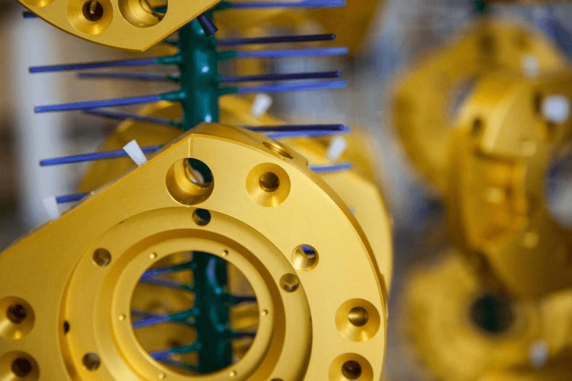
Rack marks are where current enters the part. They often look like small dull spots. Put them on a hidden face, a pocket floor, or a boss that is not the A-side. Do not put the only grounding pad and the rack on the same 4 mm island. If you leave rack location blank, the shop will clip wherever current is convenient, sometimes on your earth pad, sometimes on the A-side.
If masked aluminum also needs corrosion resistance, add a conversion-coating note on those areas. That is a different process from Type II / Type III. Keep the notes separate so plating and anodize are not mixed in one line.
For prep and color options on aluminum, use the same language as YXT anodizing finishing services so mill and bath are planned together. Alloy notes on YXT aluminum CNC machining belong in the same pack because 6061 and 7075 do not dye the same.
| Feature | Drawing action | Typical size | Best for | Watch-out |
|---|---|---|---|---|
| Ground pad | Hatch NO ANODIZE | 6-10 mm boss | Chassis earth | Pad on a thin wall |
| M3 thread | Plug or tap after | Full thread depth | Gauge after finish | Type III in the minor |
| H7 bore | Plug or after-size | Full land | Press fits | Silent 50.8 µm Type III |
| Rack-OK | Hatch C-face | ≥8 mm clip area | Hidden boss | Clip on the A-side |
| Thin window | Call min wall | ≥1.0 mm preferred | Type II cosmetics | Type III on 0.5 mm |
Bottom line: hatch pads at a maskable size, assign a different rack face, and write min wall when the skin is under about 1.5 mm.
Procedure: how to spec anodizing on a CNC drawing
Follow this order. Each step names the tool and the done check.
- Freeze alloy and temper in the title block. Tool: material note that matches the STEP stock (example: 6061-T6). Done when purchasing can buy bar or plate without asking.
- Write Type, Class, and thickness. Tool: finish flag, MIL-A-8625 Type II or III, Class 1 or 2, range in µm inside 1.8-25.4 (Type II) or 12.7-114 (Type III). Done when a finisher can select a bath without a clarifying email.
- Mark before versus after on every fit. Tool: dimension suffix or local note on bores, pins, and gauge threads. Done when a programmer knows which faces to leave undersize.
- Hatch mask zones on the PDF. Tool: 2D views with a mask legend (threads, seats, grounding) and pad sizes such as 6-10 mm. Done when a racking tech can tape or plug without guessing.
- Assign a rack-mark zone. Tool: a hatched “electrical contact OK” face that is not a ground pad. Done when cosmetics will not be argued at incoming inspection.
- Attach prep, wall, and color evidence. Tool: as-machined / blast / polish note, min wall on a section, plus a physical sample or photos of a limit panel on the same alloy. Done for Class 2 when the buyer and shop share one visual target.
- Pack the RFQ. Tool: STEP + PDF, quantity, thickness coupon, post-coat fits. Done when the factory can CAM, rack, and write a first-article plan.
Common failure: the 3D model is painted black and the PDF says “finish per model.” The PDF is the contract.
Worked RFQ example and drawing checklist
Worked example: 7075-T6 UAV plate, 180 × 120 × 6 mm, pocketed to 1.0 mm floors, 0.8 mm local windows, Type III wear on the rail, Type II cosmetics not required, two 6 mm dowel holes H7, four M4, one 8 mm earth pad on a 3 mm boss.
Finish notes that quote: 7075-T6 plate, as-machined Ra 3.2 µm on non-wear faces. MIL-A-8625 Type III Class 1, 25-50 µm, unsealed (wear). Dimensions after anodize on the rail thickness. Mask: both H7 dowels, all M4, earth pad Ø8 mm NO ANODIZE. Rack-OK: underside of the 3 mm boss, opposite the pad. Min wall 0.8 mm at windows, 1.0 mm floors, inspect after coating at named points A-F. Quantity 25. First article: thickness coupon of the same 7075 lot, wall map, continuity on the pad.
That is a Type III job with masks. The wrong version is “hard anodize black, 7075, make it light.” 7075 Class 2 black is a coupon, not a title-block adjective.
Checklist to attach with CAD:
- Alloy, temper, stock form, revision of STEP and PDF (same number).
- MIL-A-8625 Type II or III, Class 1 or 2, thickness range, sealed or not.
- Prep: as-machined Ra, bead blast, or polish.
- Before/after rule plus local notes on every fit.
- Mask legend: threads, bores, ground pads with sizes.
- Rack-OK face.
- Min wall and whether wall is post-coat.
- Color sample or limit panel if Class 2.
- Quantity, first-article coupon, continuity if grounded.
- Inspection method for thickness (eddy current or micrometer on a coupon).
Quantity belongs on the RFQ because a 5-piece prove-out and a 200-piece lot may share the same notes but not the same racking fixture. Small-batch CNC machining is the right frame when the CAD is still moving.
When the checklist is filled, send it through YXT CNC contact. CNC milling of the pockets and the anodize note have to be planned together. A long tool that tapers a 0.8 mm wall will still get coated.
What to attach with the anodize drawing
Send STEP plus PDF at the same revision, plus quantity. Do not send a STEP painted black and a PDF that says “see model.” The shop programs from the PDF notes and machines from the STEP geometry. If they disagree, the PDF should win, and you should fix the STEP.
Include a thickness coupon requirement when Class 2 lots must match or when Type III is near a fit. A coupon of the same alloy and temper is how you settle a color argument without stripping production parts. If you change from 6061-T6 bar to 6061-T6 plate mid-program, treat that as a new color lot.
If the part has Swiss-turned pins or mixed mill-turn features, still put the anodize note on the assembly or the aluminum body that actually goes in the tank. Swiss CNC machining of a pin does not replace a mask note on the housing it presses into.
FAQ
How to spec anodizing on a CNC drawing in one line?
Write alloy, MIL-A-8625 Type II or III, Class 1 or 2, thickness, seal, prep, and before/after. Then point to mask views. A complete one-liner still needs hatched pads and a rack-OK face on a 2D view. Type II stays in 1.8-25.4 µm. Type III stays in 12.7-114 µm, with 50.8 µm if you leave thickness blank. If the one-liner omits Class or thickness, the shop has to guess the bath.
Do I need MIL-A-8625 if I am not a defense program?
No. You still need Type, thickness, and Class. MIL-A-8625 is shared language that US and EU drawings already use, which is why a Dongguan shop can quote it without inventing a house spec. You can write equivalent ISO wording if you also give micrometers. You cannot write “anodize” and expect Type II 8-20 µm sealed black. Commercial parts fail the same way defense parts fail: tight bores and the wrong color.
Should I dimension before or after anodize?
Dimension after on press fits, bearing bores, and threads that must gauge. Cosmetic faces can stay before. A practical split is: after-coat on every interface that a pin, bearing, or gauge sees; before-coat on overall length of a housing that has 0.2 mm of slack. Type III at 50.8 µm makes the after-coat rule non-optional on small fits. Type II at 8-20 µm is kinder, but M3 and H7 still need a decision.
How do I call black anodize so lots match?
Call Type II Class 2 black, thickness (8-20 µm is a working 6061 window), blast or no blast, and approve a sample on the same alloy. Do not send a Pantone from a plastic chip. 7075 will not match 6061. Type III Class 2 will not match Type II Class 2. Keep the coupon with the first-article pack so lot 2 has a physical target, not a memory of lot 1.
What if I forget to mask grounding pads?
The oxide will insulate them. Put pads on the drawing before the bath. Type II at 12 µm and Type III at 50 µm are both insulators. Scratching a corner at incoming is not a process. Hatch 6-10 mm pads on bosses, keep rack marks elsewhere, and add a continuity check. If the pads must survive humidity, add conversion coating on the masked aluminum only.
How large should mask pads be on the PDF?
6-10 mm on a boss is the tape-friendly default. Many shops hold 6-8 mm without custom tooling. Smaller pads need plugs or fixtures. Sub-3 mm cosmetic islands are a dye-bleed risk. Write the size and the allowed halo (0.5-1 mm is common). Put pads on bosses, not on 0.6 mm walls. The pad size is part of how to spec anodizing on a CNC drawing, not a shop preference to settle later.
Does wall thickness belong in the anodize note?
Yes, when the skin is thin enough that the bath can move it. Call min wall on a section. Prefer Type II on 1.0 mm 6061 cosmetics. Treat Type III on walls below about 0.8 mm as a special process with a coupon. Inspect wall after coating if thickness is contractual. A title block that ignores walls will still get a film. The film will advertise oil-canning the mill did not see in the vise.
If you need a worked example of how to spec anodizing on a CNC drawing, put Type, Class, thickness (Type II 1.8-25.4 µm or Type III 12.7-114 µm), mask pads, and rack zone on the PDF, attach STEP, and send the pack to YXT CNC. The shop should not have to invent a bath from a shaded model.