Aluminum CNC design guidelines are a DFM checklist, not a slogan. Start with alloy and temper (6061-T6 for most housings, 7075-T6 when strength wins), then size internal radii to a real end mill, keep walls thick enough to cut without chatter, and reserve tight tolerances for fits. Typical published 6061-T6 tensile strength is about 45 ksi (310 MPa). Typical 7075-T6 is much higher, near 83 ksi (572 MPa), with more distortion risk in thin plates. Call Ra, anodize Type II or Type III with thickness, and which dimensions apply after coating. Send STEP plus PDF. If a feature needs a 0.2 mm internal corner, a 0.4 mm wall, and ±0.01 mm everywhere, expect extra setups, longer tools, and a quote that looks like a different part.
This is for a US or EU engineer releasing a 6061 or 7075 part to a China factory. The mill does not infer your gasket groove, Helicoil, or A-side cosmetics from a colored solid. Aluminum CNC design guidelines exist so CAM, fixturing, and finishing read the same intent.
If you are iterating a housing, treat this as the filter before aluminum CNC machining and CNC milling are quoted.
Key takeaways
- 6061-T6 is the default when you need predictable machining and Type II color. 7075-T6 is for load, not for prettier dye.
- Internal radii should match a cutter (often 1.5-3 mm), not a sharp CAD corner.
- Tight tolerances belong on datums and fits. Title-block ±0.05 mm everywhere inflates cycle time.
- Anodize growth, mask pad size, and wall thickness belong in the same guidelines.
What aluminum CNC design guidelines should freeze before CAM
What aluminum CNC design guidelines should freeze before CAM is alloy, stock, datums, tool access, and finish. If any of those is still “TBD,” the quote is a guess with a lead time attached.
Name the alloy and temper on the drawing, not only in email. 6061-T6 plate and 6061-T6 bar do not machine or relieve stress the same way on a wide, thin lid. If the part is a pocketed 200 × 150 × 8 mm cover, say plate, grain direction if it matters, and whether a stress-relief step is allowed.
Datums should match how the part sits in the product: three mutually useful planes, not six pretty faces all held to ±0.02 mm. ASME Y14.5-2018 (reaffirmed 2024) is the language for those datums. If you only need ISO general tolerances, ISO 2768-1 (1989) medium class is a known fallback for non-critical sizes. Do not mix “ISO 2768-m” with a cloud of ±0.01 mm dimensions unless you mean it.
Stock form is a design choice. Plate is the usual lid. Bar is the usual boss-heavy block. Extrusion can save pocketing if the profile already exists, but you still mill datums. Do not send “aluminum” and let purchasing pick 5052 sheet when the drawing assumes 6061-T6.
Finish is part of CAM, not a later email. Type II at 8-20 µm and Type III at 25-50 µm change how much stock you leave on a bore. A programmer who sees only “anodize black” will not leave 25 µm per side for a 50.8 µm Type III nominal.
Alloy, temper, and stock you can actually buy
In 2024 alloy tables from the Aluminum Association, typical published 6061-T6 ultimate tensile strength is about 45 ksi (310 MPa), with typical yield about 40 ksi (276 MPa). Typical 7075-T6 is far stronger, often cited near 83 ksi (572 MPa) tensile. Those are typical published ranges, not a YXT guarantee and not a substitute for the mill cert on your lot.
| Alloy / temper | Typical use | Machining | Finish | Watch-out |
|---|---|---|---|---|
| 6061-T6 | Housings, plates, brackets | Fast, stable | Type II color is predictable | Not the highest strength |
| 7075-T6 | Highly loaded plates, arms | Good, more spring | Type III wear possible; dye less even | Distortion on thin webs; poorer corrosion than 6061 |
| 6082-T6 | EU drawings that parallel 6061 | Similar to 6061 | Same finish logic | Do not mix with 6061 in one color lot |
Bottom line: pick 6061-T6 unless the load case needs 7075, and do not change alloy after you approved a Class 2 color sample.
6061-T6 is the default RFQ alloy for a reason. It cuts cleanly, takes Type II Class 2 dye in a predictable way, and is available as plate and bar in the sizes housings use. 7075-T6 is the upgrade when a bracket or arm needs the extra strength. It is not a cosmetic upgrade. Copper in 7075 often makes Class 2 color mottled compared with 6061.
If the drawing came from Europe as 6082-T6, treat it like 6061 for machining and finish logic, but do not mix 6082 and 6061 parts in one dyed lot. If you must mix, approve two coupons.
Do not specify 2024 for a wet outdoor box unless you already know the corrosion plan. 2024 machines well and anodizes, but it is not 6061 in a salt cabinet. Name the temper. T6 and T651 are not interchangeable in a stress-relieved plate conversation.
Radii, pockets, and walls that a cutter can finish
A sharp internal corner is a 0 mm tool. Real end mills have diameter. A 6 mm mill needs a 3 mm inside radius if it must reach the corner. Smaller radii need smaller tools, slower feeds, and more time. If the corner is only cosmetic, open it. If a square insert must sit in the pocket, machine a dog-bone or undercut relief and say so.
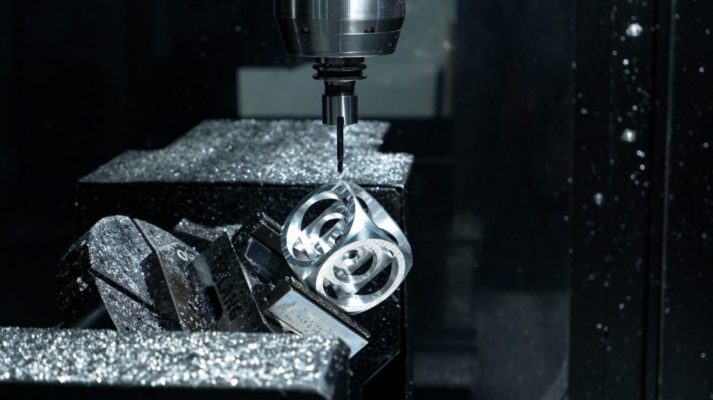
Pocket depth versus tool diameter matters. A 20 mm deep pocket with a 6 mm cutter is a long stick-out. Expect deflection and a worse floor Ra. Allow a larger cutter or split the pocket. 5-axis CNC machining helps undercuts and can shorten stick-out by tilting. It does not erase a 0.4 mm wall.
Walls: 1.5-2.0 mm is a comfortable start for 6061 housings of moderate height. 1.0 mm is common with support. Below about 0.8 mm, treat it as a thin-wall job. 0.5-0.7 mm is a local window or a 5-axis access feature, not a whole-box default. Height-to-thickness above about 10:1 chatters. A 1.0 mm wall that is 18 mm tall without ribs is a speaker cone, not a housing.
Ribs should be at least as thick as the wall they stiffen, or they become another thin wall. Fillets at the floor (1.5-3 mm) beat a sharp inside corner that a finishing mill cannot reach. If you need weight out of a lid, thin the floor in zones and keep a thicker frame, rather than taking the entire skin to 0.6 mm.
Call min wall on a section view. If you mill from both sides, show leftover floor thickness. A 6 mm plate pocketed from both sides to “1 mm remaining” is a stack-up of two depths plus cutter deflection. Put a thickness map on first article if that 1 mm is contractual.
Tolerances, threads, and finish allowance
Hold ±0.05 mm (about 0.002 in) on most milled aluminum features unless the function needs less. Push ±0.02 mm or tighter only on datums, press fits, and bearing bores, and only with a stated inspection method. A whole part at ±0.01 mm is a metrology project. 2024 manufacturing metrology notes from NIST are a reminder that you only hold what you can measure. Name CMM, gauges, or a micrometer map.
Threads: call the standard (metric coarse, UNC), depth of full thread, and whether a Helicoil or insert is installed. Leave edge distance. An M3 on a 0.8 mm wall is a cracked boss waiting for torque. A boss for M3 should have enough meat after the thread major diameter plus anodize if the hole is coated. Mask M3-M5 when Type III is on the part, or tap after coating.
Finish: as-machined Ra 3.2 µm is a normal functional default. Ra 1.6 µm is reasonable on sealing faces if you pay for the extra pass. Anodize Type II at 8-20 µm is the usual color coat on 6061 (inside the MIL-A-8625 Type II window of 1.8-25.4 µm). Type III at 25-50 µm (inside 12.7-114 µm, 50.8 µm if thickness is blank) needs allowance or mask. State before versus after coating on every fit. Link finish notes to the same discipline you use on anodizing finishing services.
Chamfers beat leftover burrs on anodized edges. A 0.2-0.5 mm × 45° break is a drawing callout, not a verbal “deburr.” Sharp edges chip in the bath and show as white lines after dye.
Mask pads for grounding should be 6-10 mm on a boss when possible. Many shops hold 6-8 mm with tape. Sub-3 mm islands are a dye-bleed risk. Put rack marks on a C-face. Do not park the only earth pad and the rack clip on the same 4 mm island.
| Feature | Start here | Tighten only if | Best for | Watch-out |
|---|---|---|---|---|
| Wall | 1.5-2.0 mm | Weight forces 1.0 mm | 6061 housings | <0.8 mm as a default skin |
| Internal radius | 1.5-3 mm | Insert needs a square corner | Pockets | 0.2 mm CAD corners |
| General tol. | ±0.05 mm | Fit or datum | Most faces | ±0.01 mm everywhere |
| Type II film | 8-20 µm | Color lot control | Visible 6061 | Blank thickness |
| Type III film | 25-50 µm | Wear faces | Slides | 50.8 µm on a press fit |
| Ground pad | 6-10 mm | EMI land is smaller | Chassis earth | Pad on a 0.6 mm web |
Bottom line: design to a cutter and a bath you can inspect, then tighten the few features that assemble.
RFQ checklist built from aluminum CNC design guidelines
Use this as the artifact you send with CAD.
- Alloy, temper, stock form (plate/bar/extrusion), and any cert requirement.
- STEP + PDF, same revision, with datums and critical fits marked.
- Internal radii listed or modeled to a real mill diameter.
- Wall thickness (min), max unsupported height, and a section at the thinnest web.
- Thread list, insert callouts, torque notes if they affect boss size.
- Surface: as-machined Ra, blast, Type II/III, thickness, mask, rack zone, pad size.
- Quantity, inspection (CMM / gauges / wall map), and whether first article is required.
Worked RFQ example: 6061-T6 instrument housing, 160 × 100 × 40 mm, 1.5 mm walls, 2.0 mm lid, internal R3, M3 corners with Helicoils, gasket groove Ra 1.6 µm, Type II Class 2 black 8-20 µm sealed, bead blast, H7 for two 5 mm dowels masked, earth pad 8 × 8 mm on an internal boss, rack-OK on the boss underside. Quantity 30. First article: CMM on datums and dowels, eddy-current thickness on a coupon, continuity on the pad.
That pack quotes as one mill-and-finish job. The same CAD with 0.5 mm walls, R0.2 corners, ±0.01 mm title block, and “anodize” is a different part. Quantity belongs on the RFQ because a 5-piece prove-out and a 200-piece lot may share the same DFM but not the same fixturing. Small-batch CNC machining is the right frame when the CAD is still moving.
When the checklist is filled, send it through YXT CNC contact.
How aluminum CNC design guidelines change after the first article
First article is where these guidelines stop being theory. If the wall map shows 0.85 mm on a 1.0 mm callout, do not “fix it in anodize.” Change the program or the design. Type II will advertise witness lines. Type III will add film on a wall that is already thin.
If Class 2 color misses the coupon, freeze blast media, Type, thickness, and alloy before you chase dye time. If a masked pad has a 2 mm halo, tighten the mask note or grow the pad to 8-10 mm. If an M3 fails a gauge, mask it on the next lot rather than chasing a 5 µm allowance that no one wrote down.
Do not change 6061 to 7075 after the color sample is approved unless you run a new coupon. Do not add Type III to a 1.0 mm lid that passed Type II without a new flatness check. The guidelines are a loop: design, quote, first article, then lock the PDF.
If the part later needs turned pins or mixed mill-turn bores, keep the housing notes on the housing drawing. CNC turning of a pin does not inherit the housing anodize spec unless you say it does.
A useful first-article pack for a 6061 housing is: CMM on datums and fits, a wall map at named points if any skin is 1.0 mm or under, eddy-current thickness on a same-lot coupon, and continuity on every masked earth pad. If Type III is on a wear rail, measure that rail after coating. If Class 2 black is on the A-side, keep the limit panel. Those four checks prevent the common loop of “color is fine, the dowel is tight, and the chassis does not earth.”
FAQ
What wall thickness should I start with on 6061?
Start at 1.5 mm for housing walls of moderate height. 1.0 mm is often holdable with support. Below about 0.8 mm you are in thin-wall process territory: lighter cuts, extra inspection, and a harder Type III story. 0.5-0.7 mm should be local. Call min wall and max unsupported height on the drawing. Stiffness drops fast as thickness drops, so a pretty CAD cut to 0.6 mm is not a free weight win.
Is 7075 always better than 6061?
No. 7075 is stronger and usually worse for corrosion, dye uniformity, and thin-plate movement. Use 7075 when the load case needs it. Keep 6061 when you want Type II Class 2 cosmetics, easier machining, and calmer lids. Typical published tensile values (about 45 ksi for 6061-T6 versus about 83 ksi for 7075-T6 in 2024 Aluminum Association tables) describe strength, not finish quality. Do not swap alloys after a color sample.
How large should internal corner radii be?
Match the finishing cutter. 1.5-3 mm covers most pockets. A 6 mm mill wants a 3 mm radius at the floor if it must finish the corner. Smaller radii mean smaller tools and more time. If a square component must sit in the pocket, add a dog-bone or undercut and call it out. A 0.2 mm CAD fillet is a 0.4 mm tool with a long cycle, not a default.
Can I put ±0.02 mm on every dimension?
You can write it. The shop will then treat almost every face as a fit. Put ±0.02 mm on the features that assemble: datums, press fits, bearing bores. Leave general sizes at ±0.05 mm or ISO 2768 medium unless function needs less. Title-block ±0.01 mm on a 200 mm plate is a CMM project. Name the inspection method when you tighten a fit.
Do aluminum CNC design guidelines include anodizing?
Yes, if the part is coated. Film thickness, mask, pad size, and post-finish dimensions are DFM. Type II 1.8-25.4 µm (practical 8-20 µm on 6061) and Type III 12.7-114 µm (often 25-50 µm, 50.8 µm if blank) change stock left on bores. Hatch 6-10 mm ground pads. Mask M3 and H7 or dimension after coating. A DFM list that stops at radii is incomplete for a black housing.
Should I send only a STEP file?
No. Send STEP plus a PDF with tolerances, threads, finish, and revision. The STEP is geometry. The PDF is the contract for Type, Class, thickness, masks, and datums. If they disagree, fix them before the RFQ. A shaded black model is not MIL-A-8625 Type II Class 2, 8-20 µm, sealed, and it does not hatch a 6-10 mm ground pad.
When do I need 5-axis instead of 3-axis?
When tool access, undercuts, or compound faces would add setups or force a long stick-out. If every face is a 3-axis plate job, stay 3-axis. 5-axis can keep a short tool in a deep pocket and protect a 1.0 mm wall. It does not replace a rib, and it does not pick Type II versus Type III. Call 5-axis when the geometry needs it, not as a quality slogan.
Apply these aluminum CNC design guidelines on the PDF before you RFQ: alloy, radii, walls, fits, Type II/III thickness, and mask pad size. Then send STEP + PDF to YXT CNC for a Dongguan process review. The quote should describe the part you drew, not the part the shop wishes you had drawn.