CNC wall thickness guidelines for milled parts are stiffness rules, not catalog minimums. For 6061-T6 aluminum, 1.5 mm is a practical short-wall target; 0.8 mm is a lower bound that often needs extra finish passes. For 304 stainless and 4140, start nearer 1.5-2.0 mm. Tall walls fail first: keep height-to-thickness near 10:1 in aluminum and nearer 8:1 in steel, or the mill will chatter. Pocket floors follow the same idea. ASME Y14.5-2018 still needs the thickness dimensioned from a datum. ISO 2768-1 (1989) will not save a 0.5 mm rib that rings like a tuning fork. These are typical shop ranges, not a guarantee on every geometry.
You are designing a milled housing, cover, or bracket that will be quoted in China. CAD will let you shell a solid to 0.4 mm. A 6 mm end mill will not finish that wall straight. Use minimums by material, then check height ratio, then write thickness on the RFQ.
Key takeaways
- Short aluminum walls at 1.5 mm usually mill clean. The same 1.5 mm at 20 mm height is a different problem.
- Steel and stainless want more thickness or less height than 6061 for the same finish.
- Pocket floors can be thinner than walls if they are supported, but a thin floor plus a thin wall is how parts twist in the vise.
- Put thickness on the PDF from a datum. “See model” is how a 1.2 mm wall becomes 0.9 mm after a late fillet.
What CNC wall thickness guidelines constrain
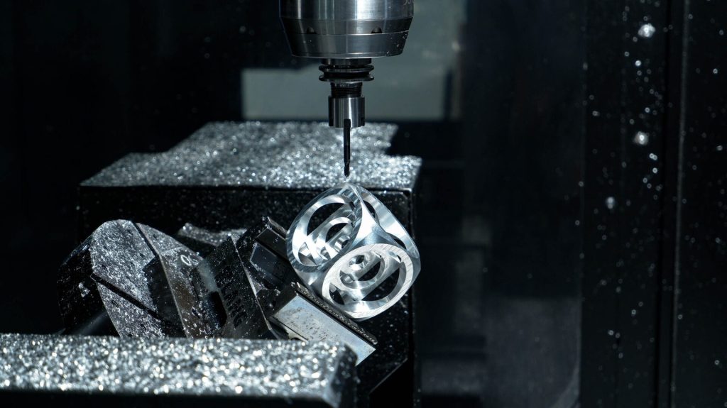
Wall thickness on a milled part constrains tool pressure, not just weight. The mill pushes sideways. A thin, tall wall spring-backs, the finish pass leaves taper, and the CMM reads out of tolerance.
The constraint is local. A 0.8 mm wall 4 mm tall on a 6061 block is often fine. A 2.0 mm wall 40 mm tall can still chatter if it is a free rib with no return flange. Height-to-thickness is the number to compute before you argue about 0.2 mm of extra stock.
ASME Y14.5-2018 wants that thickness as a dimension or a profile, not as leftover CAD. ISO 2768-1 (1989) medium class can bound a 2 mm wall. It cannot bound a wall that moves 0.15 mm under the tool. If you hold the wall to ±0.05 mm and it is 16:1 tall, you are buying spring passes, not a tighter title block.
Tool diameter ties in. A 6 mm mill taking a 0.5 mm radial finish pass still loads a 1.0 mm wall. A 2 mm mill loads it less and takes longer, and you only have a 2 mm mill if the internal fillet is about R 1 mm. CNC wall thickness guidelines and fillet choice travel together.
For aluminum CNC parts, 6061-T6 is the usual reference. 7075-T6 is stiffer, which helps a thin wall a little, but a long rib will still ring. Put the alloy and temper on the print. The Aluminum Association designations (aluminum.org) are the names to use, not “AL.”
Typical milled texture on these walls is Ra 3.2 µm. Calling Ra 0.8 µm on a 1.0 mm, 15 mm-tall rib is a second finishing problem on top of chatter.
CNC wall thickness guidelines by material
Use the table as a starting brief, then apply the height ratio in the next section. Values are typical shop ranges for 3-axis milling, not YXT guarantees and not a substitute for a load calc.
| Material | Short wall (height ≤ 8 mm) practical min | Prefer | Tall wall (height > 10× thickness) | Notes |
|---|---|---|---|---|
| 6061-T6 / 6082-T6 | 0.8 mm | 1.5 mm | Thicken, add a rib return, or shorten | Type II anodize (MIL-A-8625F, 1993) eats a few µm; do not size a 0.8 mm wall if post-coat size is critical |
| 7075-T6 | 0.8 mm | 1.5 mm | Same ratio problem as 6061 | Stiffer, still chatters as a free rib |
| 303 / 304 stainless | 1.0 mm | 1.5-2.0 mm | Prefer ≤ 8:1 height/thickness | Work hardens; skinny walls need light passes |
| 4140 / mild steel | 1.0 mm | 1.5-2.0 mm | Prefer ≤ 8:1 | Heavier cut forces than aluminum |
Bottom line: if you came for CNC wall thickness guidelines, start at 1.5 mm in aluminum for short walls, then thicken or shorten before you go under 1 mm, and give steel more than you give 6061.
CNC milling quotes assume the wall can take a realistic radial width of cut. If it cannot, the shop adds spring passes. A 6 mm mill at 4:1 L/D in 6061 is a normal finishing tool on a 1.5 mm wall. The same mill on a 0.7 mm wall is a spring pass, then another, then a CMM fail on taper.
303 taps and mills easier than 304. If you picked 304 for corrosion, keep 304 and thicken the wall. Do not thin a 304 rib to 0.8 mm because a 6061 version of the same CAD survived.
On mill-turn parts, a turned tube wall is a different stiffness problem (boring-bar push). A Ø20 mm ID with 1.0 mm wall is a thin cylinder. Keep boring L/D near 4:1 or the ID tapers. Put that on the CNC turning view, not only on the mill pocket.
Height-to-thickness ratio and chatter
Compute h/t on the tallest free wall: height from the supported root to the free edge, divided by local thickness.
For 6061, treat about 10:1 as the point where you should change the design or accept extra finish time in writing. A 15 mm-tall, 1.5 mm wall is 10:1. A 20 mm-tall, 1.2 mm wall is already 16:1. That second wall is where taper shows up. ISO 2768-m might allow ±0.2 mm on that height. Your wall callout of ±0.05 mm will not survive 16:1 without extra passes.
For 304 and 4140, treat about 8:1 as the same decision point. Stainless work-hardens if the mill rubs. A thin wall that needs a light cut is that rubbing condition. A 12 mm-tall, 1.2 mm 304 wall is 10:1: already past the steel preference.
Fixes that work, in order: thicken the wall locally; add a return flange or connecting rib; shorten the pocket so h drops; mill from both sides if a through is allowed.
Do not use 5-axis as the thickness fix. Tilt can shorten stick-out. It does not make a 0.5 mm blade stiff. 5-axis CNC machining helps when the wall is on a compound face, not when the wall is too thin.
Support changes the ratio. A wall with a return flange at the top is not a free cantilever. Compute h to the last supported edge. A box section with four walls is stiffer than a single rib of the same t. CNC wall thickness guidelines are for the free case. If you add a lid or a rib grid, you can often stay at 1.5 mm.
Ribs, floors, and bosses
Pocket floors. A floor can be thinner than a free wall because the floor is supported around its edges. 1.0-1.5 mm floors in aluminum are common on covers. A 0.5 mm floor over a 60 mm span will dish under the mill. If you need a light cover, add shallow ribs or thicken the floor. Span matters more than t. A 1.0 mm floor over 20 mm is usually fine in 6061. A 1.0 mm floor over 80 mm is a drum.
Ribs. Treat a rib as a wall with two free faces. The same h/t limit applies. A slightly thicker root helps. A 2.0 mm root tapering to 1.5 mm at the tip mills cleaner than a 1.5 mm blade all the way down.
Bosses. A boss with 1 mm wall around an M4 insert will walk. Leave 1.5-2.0 mm radial stock around small threads in aluminum, more in stainless. Blind threads in thin floors need depth and a relief. M4x0.7 in a 1.2 mm floor does not have thread depth. Either boss the floor locally to 6-8 mm or use a shorter fastener.
Internal corners. Thin walls plus sharp corners stack two problems: a small mill and a flexible wall. Give the pocket a fillet that matches a 6 mm mill (about 3 mm R, preferably 3.5-4.0 mm). A 1 mm mill finishing a 0.8 mm wall is how both features fail together.
Turned thin walls. If a mill-turn housing is a cup, the bored ID is the floor/wall cousin. Keep 1.5-2.0 mm in aluminum for a short cup. A 0.8 mm cup 25 mm tall will ring on the boring bar.
What to put on the drawing and RFQ
Take this as the workpiece from the guide.
- Dimension the critical wall from a datum (not “see STEP”). You are done when a CMM can report thickness without probing the model.
- Dimension the tallest rib height so h/t is visible. You are done when a second engineer can compute the ratio from the PDF.
- Name the alloy and temper. You are done when the stock list matches the title block.
- State whether sizes apply before or after coat. You are done when finishing would not guess.
- If you must keep a thin tall wall, note extra finish passes so the quote includes the time.
- Export PDF and STEP at the same revision.
- Call default Ra 3.2 µm on walls; leader-line Ra 0.8 µm only if a seal needs it.
- Call internal R so the mill that finishes the wall is not a 1 mm tool. You are done when wall t and mill Ø are compatible.
For a 10-piece bridge, still dimension the wall. Small-batch CNC machining will inspect the same thin rib you hoped nobody would measure.
When the brief is filled, send quantity, material, and the PDF through YXT CNC contact. If the wall is load-bearing, say so. ISO 2768-m is for non-mating thickness. If the wall is a seal land, give a real tolerance and a datum.
| h (free height) | t = 0.8 mm (h/t) | t = 1.5 mm (h/t) | t = 2.0 mm (h/t) | 6061 action |
|---|---|---|---|---|
| 6 mm | 7.5:1, usually OK short | 4:1, easy | 3:1, easy | 0.8 mm only if short and not a fit |
| 12 mm | 15:1, taper risk | 8:1, OK | 6:1, OK | Prefer 1.5 mm |
| 18 mm | 22:1, do not | 12:1, extra passes | 9:1, borderline 10:1 | Thicken or shorten |
| 24 mm | 30:1, do not | 16:1, do not as free rib | 12:1, add return | Redesign |
Bottom line: read the h/t cell before you argue about 0.2 mm of CAD shell thickness.
Worked RFQ.
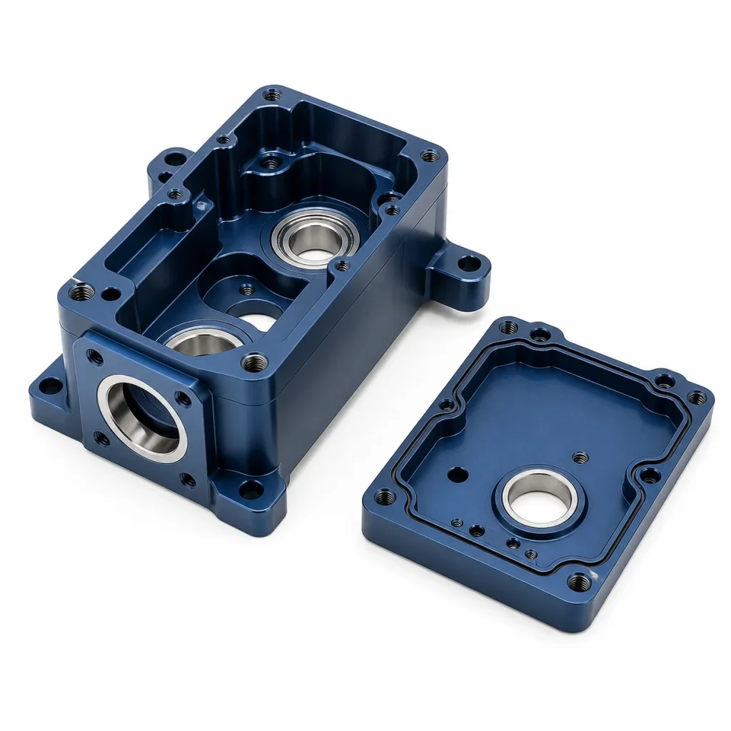
A EU mechanical engineer sent quantity 30 of a 6082-T6 electronics cover, STEP plus PDF, Type II black, sizes after coat. The CAD shell was 0.8 mm everywhere: side walls 18 mm tall (22.5:1), floor 0.8 mm over a 72 x 50 mm span, four M3 bosses with about 1.0 mm radial wall.
Pack 1 (Rev A) used ISO 2768-m and a title-block ±0.1 mm on wall thickness. The mill could see the 0.8 mm shell in the STEP. They had to assume spring passes, possible taper outside ±0.1 mm, dish in the floor under a 6 mm mill, and Type II rack scuff on a knife edge. Internal corners were R 0.5 mm, so the finishing mill was also small.
Pack 2 (Rev B) after this guide: side walls 1.6 mm (h/t 11.25:1, still a bit tall; a 4 mm return flange was added at the open edge so the free height dropped to about 14 mm effective, h/t nearer 9:1); floor 1.5 mm with two 1.5 mm-tall ribs across the 72 mm span; bosses 2.0 mm radial around M3x0.5-6H; internal R 3.5 mm; 6082-T6 named; Ra 3.2 µm; Type II black per MIL-A-8625F (1993), 5-25 µm, sizes before coat, gasket land masked; wall thickness dimensioned from datum A. Quantity stayed 30. Envelope grew 0.8 mm inward; the board still cleared.
The quote moved because the mill could finish with a 6 mm tool at reasonable L/D, skip most spring passes, and inspect a dimensioned 1.6 mm wall instead of a moving 0.8 mm blade. Floor dish risk dropped with the ribs. No unit price is published here.
Failure case: Rev B thickened the walls in CAD but left the PDF dimension at 0.8 mm. The shop quoted and inspected 0.8 mm. The STEP was “what we meant.” Overlay thickness, not only holes. Incoterms 2020 on the email did not fix that mismatch.
FAQ
What is the minimum wall thickness for CNC aluminum?
There is no single mill-standard minimum. 0.8 mm is a common lower bound for short 6061 walls. 1.5 mm is the practical target for most housings. Short means height around 8 mm or less, so h/t stays near 10:1 or better. A 0.8 mm wall 20 mm tall is not that lower bound; it is a chatter feature. 7075-T6 may finish a short 0.8 mm wall a bit cleaner because it is stiffer, but it still rings as a free rib. Dimension the wall from a datum and name the temper. “Make it as thin as you can” is not a quote input.
Do CNC wall thickness guidelines change for 7075 vs 6061?
A little. 7075-T6 is stronger and a bit stiffer, so a short thin wall may finish cleaner. Tall free ribs still chatter. Treat 10:1 as the same decision point unless you have a return flange. Do not cut a 7075 wall to 0.5 mm because the alloy number looks stronger. Cut forces and tool L/D still apply. If you swapped to 7075 only for stiffness of a 0.8 mm, 18 mm rib, thickening the 6061 wall to 1.6 mm is usually the cheaper stiffness move.
Can I mill 0.5 mm walls if I only need a prototype?
You can ask. The shop will quote extra passes and higher scrap risk. For a prototype that must match production, use the production thickness. A 0.5 mm 6061 wall 10 mm tall is 20:1. It can be made with tiny radial passes and a small mill, which is the opposite of a fast prototype. If the prototype is a fit check, 1.5 mm walls will teach you more about the assembly and less about shop heroics. Small-batch CNC machining still inspects the wall you drew.
How thin can a pocket floor be?
In aluminum, 1.0 mm is a common practical floor on small spans. Large spans need ribs or more thickness. Measure span, not only t. A 1.0 mm floor over 25 mm in 6061 is a normal cover. A 1.0 mm floor over 80 mm will dish under a 6 mm mill and show a convex CMM map. Add 1.5 mm ribs or thicken to 1.5-2.0 mm. In 304, start nearer 1.5 mm even on small spans. If the floor also holds a blind thread, boss locally; do not tap M4 in a 1.0 mm membrane.
Does anodize mean I should thicken the wall?
If you inspect after coat and the wall is already near 0.8 mm, design to the post-coat size. Type II buildup is small, but a knife-edge wall still scuffs on the rack. MIL-A-8625F (1993) Type II films are often 5-25 µm. That will not turn a 1.5 mm wall into a problem. It will make a 0.6 mm blade fragile in handling. Mask seal lands. Say whether wall thickness applies before or after coat so ISO 2768-m is not fighting dye.
Can I use ISO 2768-m as my wall tolerance?
Yes on non-mating walls that are stiff enough to mill without moving. No on a 16:1 rib you also hold to a fit. ISO 2768-1 (1989) medium class on a 1.5 mm wall is a linear general tolerance on a feature that must not flex 0.1 mm under the tool. If the wall is a gasket land, use a tighter local tolerance, a datum, and Ra 0.8 µm if you need it. If the wall is only a cover side, ISO 2768-m plus 1.5 mm thickness is the usual export package.
Do these guidelines apply to turned cups and tubes?
Yes in spirit: boring-bar push tapers a thin wall the same way a mill does. Keep wall t in the 1.5-2.0 mm range for short aluminum cups, and keep bore L/D near 4:1. A Ø16 mm ID, 1.0 mm wall, 30 mm deep is a thin tube at about 1.9:1 on diameter but 30:1 on unsupported length as a bell. Support it, thicken it, or machine it as two pieces. Put the wall on the PDF from the axis datum. Do not leave the cup as a shelled solid with no thickness dimension.
Use these CNC wall thickness guidelines as a brief: 1.5 mm short aluminum walls, more thickness or less height for steel, and an h/t check on every free rib. Dimension the wall on the PDF, match the STEP, and send the pack to YXT CNC contact with alloy, quantity, and whether coating applies before or after size.