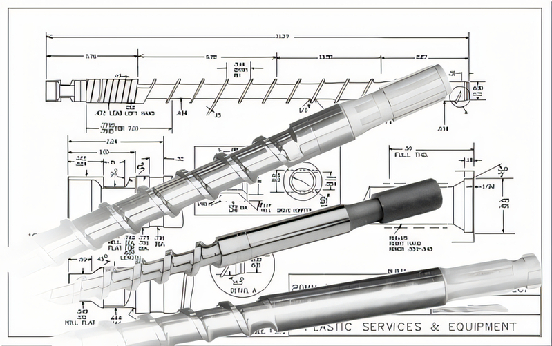
How to dimension a CNC drawing for quote is a documentation job, not a styling job. The PDF must carry a datum scheme, overall size, hole locations, thread callouts (class and depth), a general tolerance such as ISO 2768-1 (1989) medium class, surface texture (Ra 3.2 µm unless a face needs better), and a named alloy plus temper. ASME Y14.5-2018 is the usual US GD&T language for the fits. Send the STEP as geometry, not as a substitute for those notes. If a mating feature has no dimension, the estimator will apply the title-block default. That is how quotes and first articles diverge.
You are sending an RFQ to a China mill from a US or EU desk. The shop will not infer a bearing bore from a pretty section view. They will price what is written, then inspect what is written.
This page is the dimension-and-note list for a quote pack. Hold the fits. Open the air. Name the coat.
Key takeaways
- Quote drawings need datums, overall envelope, and every mating hole or thread. Cosmetic edges can live on ISO 2768.
- The STEP is the shape. The PDF is the contract. If they disagree, the shop prices the riskier file.
- Ra, anodize type, and “before or after coat” belong on the sheet, not in a chat the estimator never sees.
- A 7-step CAD pass is enough for most 3-axis parts. You are done when a second engineer can quote without asking what a hole is.
What a quote drawing must carry before you send it
A quote drawing is the minimum set of dimensions and notes that lets a mill pick tools, setups, and inspection.
ASME Y14.5-2018 tells you how to state datums and feature controls. ISO 2768-1 (1989) tells you what to do with everything you did not tighten. Do not paste ±0.02 mm in the title block “to be safe.” That line adds finishing on faces that never mate. On a 40-80 mm non-mating outline, ISO 2768-m is typically ±0.3 mm. A 3-axis mill in 6061-T6 holds that on a standard pass at Ra 3.2 µm. Title-block ±0.05 mm on the same outline is extra finish time plus extra CMM points.
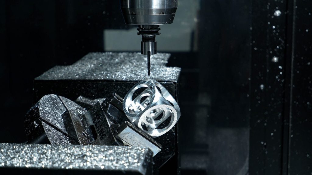
The drawing also has to imply a tool. If a pocket has no internal radius, the programmer assumes the CAD corner is real and picks a 1 mm or 2 mm mill. If the pocket is 20 mm deep, that is 10:1 to 20:1 L/D. If you dimension R 3.5 mm, a 6 mm mill can finish the corner at about 3.3:1. How to dimension a CNC drawing for quote is how you stop that tool choice from being a guess.
If the job is a first ten pieces, still dimension it as if small-batch CNC machining will inspect it. Quantity does not replace a missing H7.
How to dimension a CNC drawing for quote: datums and overall size
Start with the faces the part sits on and the envelope the mill has to buy as stock.
Put datum A on the primary functional plane. Put B and C on features that clock the part, not on a decorative chamfer. Then give overall length, width, and height from those datums. Stock size and vise choice come from the envelope. A housing that is 82 x 54 x 18 mm from A/B/C is plate work. A shaft that is Ø24 x 90 mm is bar work for CNC turning. If you omit the envelope, purchasing measures the STEP bounding box and may add 3 mm of extra stock you will pay to mill off.
If you use true position on a hole pattern, the datum reference frame must match how the assembly locates. A pattern dimensioned to a raw sawed edge will pass CMM and fail the fixture. Under ASME Y14.5-2018, the order A|B|C is the setup order. If the plate sits on A and locates to two dowels, those dowels belong in the frame. Do not put datum B on a cosmetic side wall just because it is easy to probe.
For turned diameters that later mill, show the turned size and the milled flats on the same sheet so turning and milling estimators are not quoting two different shafts. Call runout or concentricity to the axis datum on bearing seats. A typical turned bearing OD might be Ø20 g6 with 0.02 mm runout to datum A. ISO 2768-m will not hold that fit. Write the fit. Put 6061-T6 plate or bar in the title block, not “AL.”
How to dimension a CNC drawing for quote: holes, threads, and pockets
Holes and pockets are where missing numbers cost money.
Every through hole needs diameter and location. Every blind hole needs diameter, depth, and a note if the drill point may go below the useful depth. Every tap needs a thread callout with class (M6x1-6H or 1/4-20 UNC-2B), hole depth, and thread depth. Pretending the thread goes to a sharp 90° floor is how taps break. A common M6x1 blind boss: Ø5.0 tap drill, 12 mm hole depth, 9 mm thread depth, 6H. That leaves incomplete thread and chip room. Calling 12 mm full thread in a 12 mm hole is a broken tap.
Pockets need depth from a named face. Internal fillets should be dimensioned or defaulted, because a 0 mm CAD corner is not a mill. If two pockets share a thin wall, dimension the wall. Depth 16 mm from datum A, internal R 3.5 mm, wall 1.5 mm: a programmer can pick a 6 mm mill at about 2.7:1 L/D. Depth 16 mm, R 0.5 mm, wall 0.8 mm: that is a 1 mm mill at 16:1 plus chatter on the wall.
Hole tables save RFQs. List: hole ID, qty, size or thread, depth, from-datums coordinates. A 4x Ø3.4 through at a 40 mm square pattern with position Ø0.1 mm to A|B|C is quoteable. “4 holes, see model” is not.
On lathe parts, dimension groove width, groove diameter, and corner radii the insert can leave. A 3 mm-wide groove with R 0.2 mm corners may need a special insert. R 0.4-0.5 mm is a stock groover for many shops. Bore L/D near 4:1 keeps a standard boring bar. Ø10 mm x 45 mm deep is 4.5:1; say if a drill point may break through.
For CNC milling housings, clearance holes should be drill-chart sizes (Ø3.4, Ø4.5, Ø6.6) unless they are fits. Custom Ø4.15 mm is a reamer or a bore.
Finish, material, and general-tolerance notes
Material is an alloy plus temper: 6061-T6, 7075-T6, 304, 303, 4140. “AL” and “SS” are not quotes.
As-machined milled faces are commonly Ra 3.2 µm. Call Ra 1.6 or 0.8 only on the faces that need it. A blanket Ra 0.8 is a polishing job hiding in a milling quote. Turned ODs often ship at Ra 1.6-3.2 µm. Ra 0.4 µm on an OD is grind or polish unless you only need it on a seal journal. Put the fine Ra on a leader line to that journal, not in the title block.
If you coat, name the process. Type II anodize at 5-25 µm is a typical MIL-A-8625F (1993) sulfuric range. Say whether dimensions apply before or after coat, and which faces to mask. An H7 bore that must stay H7 after coat is either masked or sized after. A gasket face at Ra 0.8 µm that also takes dye needs a mask note or you will argue about pits and dye bleed.
General tolerance: ISO 2768-m is the usual export default. If your company is inch-based, write the equivalent on the sheet. Do not mix a metric ISO block with inch plus-minus unless you say which rule wins. Typical ISO 2768-m (1989): ±0.1 mm on many 6-30 mm linear features, ±0.2 mm on 30-120 mm. ISO 2768-f is tighter and will add time. Use it only if the whole part is a fit.
A 7-step procedure you can run in CAD
Run these steps on the PDF you will export. The STEP is a check, not a shortcut.
- Lock the revision. Set the same revision string on the drawing title block and the STEP filename. You are done when both files open with one ID and one date. Failure:
plate_revD.stepzipped withplate_revC.pdf. The shop quotes the PDF and machines a hole the model already moved.
- Place datums A, B, and C. Use the mating plane and two clocking features. You are done when a CMM programmer could write a setup sheet from the PDF alone. Tool: the assembly, not the CAD screenshot orientation.
- Add overall envelope dimensions. Length, width, height from the datums. You are done when purchasing can pick bar or plate without measuring the model by eye. Include a stock note if leftover mill stock on a sawed face is not allowed.
- Dimension every hole and thread. Diameter or thread class, depth, and location. You are done when no hole exists only in the 3D body. Include incomplete-thread allowance on blinds (about 2.5-3 pitches for many metric taps).
- Dimension pocket depths and internal radii. Depth from a named face; fillet value or a note “sharp, EDM.” You are done when a programmer knows whether a 3 mm radius is allowed. Prefer R ≥ mill radius, plus 0.5-1.0 mm if a finisher must clean the wall.
- Write material, Ra, and coating. Alloy-temper, default Ra, any better faces, anodize or passivate, mask. You are done when finishing would not have to ask a question. State before/after coat for sizes.
- Overlay STEP vs PDF. Compare silhouettes and hole counts. You are done when a second person finds zero conflicts. Check the tightest internal R in both files. A PDF note “R 3.5 unless noted” with a STEP still at R 0.3 mm is a conflict.
When the pack is clean, send it with quantity and finish through YXT CNC contact.
| Feature | Must-have on the quote PDF | Shop assumption if missing |
|---|---|---|
| Datums | A/B/C and how the part sits | Vise face equals datum A |
| Envelope | L x W x H from datums | Stock guessed from the STEP box |
| Holes | Dia, location, depth if blind | Model hole, general tolerance |
| Threads | Class, hole depth, thread depth | “Some M6,” tap to floor |
| Pockets | Depth, fillet or EDM note | Sharp CAD corner, tiny mill |
| Material | Alloy plus temper | Cheapest cuttable stock |
| Finish | Ra default plus coat / mask | As-machined, no coat |
Bottom line: if the right-hand column would wreck a fit, put the left-hand callout on the sheet before you RFQ.
| Dimension type | Typical quote default if you stay silent | Write this instead | ||
|---|---|---|---|---|
| Non-mating outline 40-80 mm | House ±0.1 mm or tighter “to be safe” | ISO 2768-m (1989) | ||
| Mating bore | Model size, no fit class | Ø20 H7 or the fit you need | ||
| Hole pattern | XY from a random origin | Position to A | B | C |
| Internal corner | CAD R 0-0.5 mm, 1 mm mill | R 3.5 mm (6 mm mill) | ||
| Blind thread | Tap to modeled floor | M6x1-6H, hole 12, thread 9 | ||
| Milled texture | Ra 3.2 µm guessed, or Ra 0.8 feared | Ra 3.2 default, Ra 0.8 on gasket only | ||
| Turned OD | Ra 1.6 µm guessed | Ra 1.6 or 3.2, plus seal journal if needed |
Bottom line: dimension the left-hand risk, not every cosmetic edge.
Worked RFQ.
A EU design engineer sent quantity 12 of a 6082-T6 adapter plate plus a 304 stainless pin, one zip, asking how to dimension a CNC drawing for quote so both pieces could be priced together.
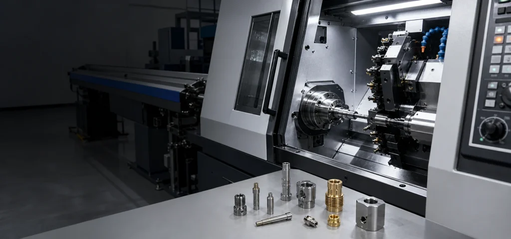
Pack 1 (Rev A): one STEP of the plate, no PDF; pin was a second STEP named shaft_final.step with no drawing. Title in the email: “aluminum plate and SS pin, as machined.” The mill could see a 70 x 48 x 12 mm plate with six holes and a Ø8 x 35 mm pin. They could not see fits, threads, or which plate face was datum A.
What blocked a contract quote: plate holes were Ø5.0 in the model (looked like an M6 tap drill) but the email said “M6 through”; no thread depth because they were modeled as through solids; no ISO 2768 block; pin had a Ø8.00 cylinder with no g6/h6 and no runout; one plate pocket had R 0.2 mm in CAD.
Pack 2 (Rev B) after the 7-step pass: plate PDF with datum A on the mating face, B and C on two edges that match the assembly fixture; overall 70 x 48 x 12 from datums; 4x Ø6.6 through (M6 clearance) at a 40 x 30 pattern, position Ø0.15 mm to A|B|C; 2x M6x1-6H through; pocket 6 mm deep from A, internal R 3.5 mm; ISO 2768-m; 6082-T6; Ra 3.2 µm; STEP filename matching Rev B. Pin PDF: Ø8 g6 x 35 mm, 0.02 mm runout to datum axis A, 3 mm groove 2 mm from the head with R 0.4 mm corners, Ra 1.6 µm on the OD, 304.
The quote changed because the plate became 3-axis work with a 6 mm mill instead of a 1 mm corner-clean, the two M6 holes became taps instead of clearance (or the reverse of the email-vs-model fight), and the pin became a defined turned fit instead of “Ø8 stainless.” Quantity stayed 12. No dollar figure belongs here; the handle was missing callouts, not freight.
Second failure case: Rev B PDF was correct, but the pin STEP still showed a sharp groove corner. The lathe programmer trusted the STEP, used a pointed tool, and the first article groove did not match the PDF R 0.4 mm. Overlay both parts, not only the plate.
If Incoterms 2020 matters (EXW vs DAP), put it in the RFQ email next to quantity. It does not replace Ø8 g6.
FAQ
How to dimension a CNC drawing for quote if I only have a STEP file?
Build a one-sheet PDF that carries datums, envelope, holes, threads, material, and finish, then export a matching STEP. A bare STEP can get a rough number. It is not a contract. The model will not tell the mill M8x1.25-6H, ISO 2768-m, or Ra 0.8 µm on one face. CAD fillets at R 0.3 mm will also look like a real mill requirement. Export the PDF from the same revision, overlay hole count, and send both files. If you cannot dimension a feature, you are not ready to RFQ that feature.
Do I need every fillet dimensioned?
No. You need a default internal radius note plus dimensions on fillets that are functional or that force a special mill. “Internal R 1.5 unless noted” covers most pockets only if 1.5 mm is really what you want (a 3 mm mill). For 3-axis aluminum housings, “internal R 3.5 unless noted” is a more practical default because a 6 mm mill can finish it. Dimension a smaller R only on the corners that must be small, and accept the L/D cost. External fillets and edge breaks can stay on a general note (0.2-0.5 mm).
Is ISO 2768 enough without GD&T?
Often yes for plates, spacers, and covers. No when a hole pattern must match a mating part. Then add position or profile to those features and leave ISO 2768-1 (1989) on the rest. ASME Y14.5-2018 is the usual language for that position callout on US drawings. A 4-hole pattern at ±0.1 mm XY each is not the same as position Ø0.1 mm to A|B|C; the shop will inspect whichever you wrote. If you wrote neither, they inspect the title block, which may be tighter than the mate needs.
Can I write “see 3D model” for complex surfacing?
You can for organic faces you will accept as-modelled, if you also give a profile tolerance and a datum frame. “See model” with no tolerance is how first articles fail. Profile 0.2 mm to A|B|C on a 5-axis surface is a contract. “See model” on a pocket floor that also has a seal groove is a fight. Keep holes, threads, and gasket Ra on the PDF even when a surface is model-controlled. 5-axis CNC machining still needs that profile number.
What thread note do Chinese mills expect on a metric drawing?
A full ISO callout: M8x1.25-6H, hole depth, thread depth. “M8” alone is a guess. For inch threads, include UNC/UNF and class. Add a note if the thread is through or blind, and if a thread mill is required (fine pitch, large Ø, or interrupted). Incomplete thread at a shoulder should be shown or allowed in a note. Helicoil or insert callouts need the tap drill and the insert standard, not only “insert.”
Should I dimension stock size or finished size?
Dimension finished size from the datums, then add a stock or material note so purchasing can buy plate or bar. The mill quotes finished geometry. If you only give a 100 mm STEP box, they may buy 100 mm stock and leave a sawed face, or they may buy 105 mm and mill all around. If all-around mill is required, say “mill all faces” and give the finished envelope. If a sawed face is allowed, datum that face or leave it as stock with a note.
How do I dimension a mill-turn part on one PDF?
Show the turned diameters, groove widths, and axis datum on the left, and the milled flats, holes, and pockets on the same sheet with the same revision. Estimators should not need two files to learn that a Ø20 g6 shaft also has a 12 mm-wide milled pad. Call runout on the turned seats and true position on the milled hole pattern to that axis if they share a stack. Default Ra can differ: Ra 1.6 µm turned, Ra 3.2 µm milled, unless a face needs better.
What belongs in the title block vs a local note?
Title block: alloy-temper, ISO 2768-m, default Ra, default internal R, coat process, units, revision. Local notes: H7, position, Ra 0.8 µm gasket, mask, EDM, thread depths. If you put Ra 0.8 µm in the title block, the whole part becomes a finishing job. If you put ISO 2768-m in the title block and then ±0.02 mm on every linear dimension anyway, the title block is decoration. Pick one general rule, then exception-note the fits.
If you came here for how to dimension a CNC drawing for quote, run the 7-step pass, export matching PDF and STEP, and send quantity plus finish with the pack. Contact YXT CNC when you want that pack priced as milling and turning work, not as a guess from an unlabeled model.