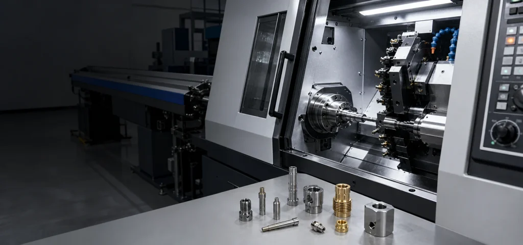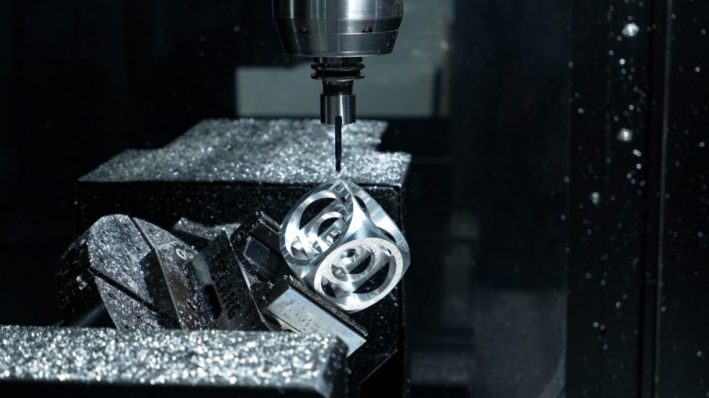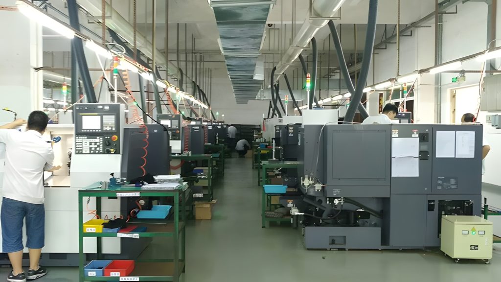
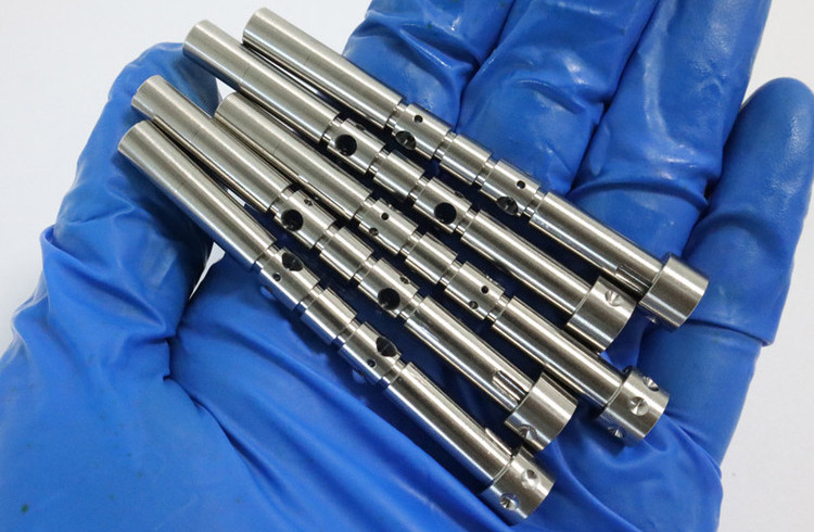
CNC turning length to diameter ratio (L/D) is a stiffness problem on the lathe, not a brand of machine. Unsupported bar or a slender 4140, 304, or 6061-T6 shaft will chatter, taper, and lose roundness as L/D grows. As a planning start, many shops treat L/D near 3:1 as chuck-only, add a tailstock as the ratio climbs, and look at a steady rest or a redesigned step when the part gets long and thin. ASME Y14.5-2018 still needs datums on the journals you care about. ISO 2768-1 (1989) will not save a tapered OD. Design the support, do not only tighten the tolerance.
You are releasing a shaft or a pin-like turning to a China factory and the model is long compared with its diameter. This page is DFM for that ratio on a chuck or collet lathe. It is not the page that chooses Swiss as a process family, and it is not a runout-symbol tutorial.
Send overall length, smallest diameter, and how the part is gripped. The shop will read L/D before it promises a straight journal.
Key takeaways
- L/D is finished length divided by the diameter that is actually cutting, not the flange you grip.
- Plan support before you plan a tighter OD tolerance.
- Steps, a larger grip diameter, and a center hole are design tools, not decorations.
- A general size class does not control taper on a slender bar.
- If you cannot add support, change the geometry or accept a different process cell.
How to calculate CNC turning length to diameter ratio
How to calculate CNC turning length to diameter ratio is finished unsupported length over the diameter being cut, using the same units.
Use the smallest diameter that exists over the long span, not the chucking flange. A 12 mm journal that runs 80 mm past the chuck is L/D ≈ 6.7 even if a 30 mm head is in the collet. Centers, if you machine them, change the support story. They do not change the raw ratio until they are in the process.
Write both numbers on the RFQ. “Long shaft” is not a ratio. 80 mm over Ø12 mm is.
Stock stick-out during roughing can be worse than the finished ratio. The shop may leave extra bar, rough the OD, then face to length. If roughing stick-out is 120 mm on Ø12 mm bar, the process L/D is 10:1 even if the finished part is 80 mm. That is why a mild finished ratio can still need a tailstock.
Do not average diameters. A 20 mm body with a 8 mm stem over 60 mm is not “Ø14 effective.” The stem is 7.5:1 and will chatter first. Compute L/D on the weakest span the tool must cut.
Tube walls have a second ratio: length over wall thickness, plus ID support. A long 1 mm wall on Ø20 mm tube is not a solid-shaft problem. It may need a mandrel or a rest. Say if a mandrel is allowed.
Units must match. 3.15 in over Ø0.375 in is 8.4:1, same math as millimetres. Put units in the title block so nobody mixes inch length with millimetre diameter.
CNC turning length to diameter ratio versus support method
CNC turning length to diameter ratio versus support method is the table you should use before you freeze the solid.
| L/D (planning band) | Typical support | What the shop is guarding | Best design move | Watch-out |
|---|---|---|---|---|
| Up to about 3:1 | Chuck or collet | Normal OD turning | Keep a grip diameter | Do not add a center you will never use |
| About 3:1 to 6:1 | Tailstock center | Taper and chatter | Add a center hole or a stub the center can see | A closed end needs a process note |
| About 6:1 to 10:1 | Tailstock plus careful passes; maybe a rest | Push-off and taper | Add a step or a steady-rest diameter | Tight Ra on the thin span fights the tool |
| Beyond about 10:1 | Rest, redesigned geometry, or another cell | Deflection that a pass cannot hide | Shorten, step, or change process | Copying a tight OD from a stiff shaft will fail |
Bottom line: treat those bands as planning starts, not as YXT guarantees. Geometry, material, and grip still win or lose the part.
The Aluminum Association lists 6061 and 7075 designations used on mill certs (current alloy information on aluminum.org as of 2024) (Aluminum Association). 6061-T6 is easier to cut than 304 in a slender span, but it still bends. ISO 2768-1 (1989) can cover the lengths you did not otherwise limit (ISO 2768-1). It will not hold a journal that tapers from deflection.
A second table maps bar diameter to cell once L/D is known.
| Bar / largest OD | High L/D implication | Typical cell |
|---|---|---|
| About Ø3–16 mm bar, slender, both ends live | Bushing keeps the cut short | Swiss with live tools if holes exist |
| About Ø16–40 mm, moderate L/D | Tailstock on a chuck lathe | Conventional turning, live-tool keyway OK |
| Flange or blank above Swiss bar | Bushing will not swallow the head | Chuck or mill-turn, never force Swiss |
| Tiny mill hole on high L/D pin | Vise will bend the pin | Driven tool on Swiss or chuck, not a mill split |
If the part is still a lathe family, keep it on CNC turning services and put the L/D numbers in the notes.
Design moves that lower the ratio the shop has to fight
Design moves that lower the ratio the shop has to fight are geometry changes, not CAM tricks.
Add a step so the thin span is shorter. Leave a larger diameter where a steady rest can ride, then machine it away only if the print allows. Put a center hole in an end that can accept one. Avoid a sudden 1 mm wall on a long tube unless you accept a mandrel or a rest.
Fillets at shoulders help the tool and fatigue life. A sharp internal corner on a slender 4140 shaft is a tool-radius fight. Call a radius the insert can cut. Brass often cuts with less push-off. Annealed stainless can push the tool and leave taper. None of that deletes L/D.
A larger grip diameter is free stiffness if the assembly can live with a head. Changing Ø10 mm × 90 mm into Ø16 mm head × Ø10 mm × 50 mm stem cuts the dangerous span. If the assembly cannot accept a head, you need support or another cell.
Do not specify Ra 0.8 on the thin span as a substitute for stiffness. Extra passes add time and can add push-off. Put Ra 1.6 on journals if that is what the bearing needs, and allow support.
If the diameter is small, the bar is long, and a guide bushing would keep the cut short, Swiss becomes a later candidate. Make the chuck-lathe ratio survivable first, or switch cells on purpose. For aluminum slender parts, keep aluminum CNC machining beside the grade callout.
Live tooling on a high L/D chuck shaft adds side load. A cross-hole drill can push the bar. If you need that hole, either shorten the stick-out, use Swiss so the bushing sits next to the cut, or accept a rest. Do not treat mill-turn as a free feature on a 10:1 pin.
Runout, bar diameter, and stock stick-out on slender turnings
Runout, bar diameter, and stock stick-out are the inspection and stock facts that travel with CNC turning length to diameter ratio.
Taper from deflection shows up as size along the cylinder and as total runout. Circular runout on one belt can pass while the journal is banana-shaped. If the journal spins in a bearing, put circular or total runout to a real datum, not a note that says “straight.” ASME Y14.5-2018 is the usual US language for that frame (ASME Y14.5). Old concentricity notes do not tell the shop to use an indicator on a V-block.
Bar diameter is not L/D, but it picks the cell. Ø8 mm × 70 mm 303 is high L/D in a chuck and a normal Swiss candidate. Ø28 mm × 90 mm 4140 is about 3.2:1 and a chuck plus tailstock job. Same “long shaft” email, different math. Write largest OD and thin diameter. Swiss bushings want consistent bar. If you require ground bar, say so. If the largest feature is a flange the bushing cannot swallow, stay on the chuck.
Stock stick-out is the process L/D. Tell the shop if a center hole is allowed. Tell them if a rest diameter can remain as a non-functional ring. Forbidding both on a 8:1 span is a design decision. Own it on the PDF.
Reclamping a slender shaft to turn the back end is how runout dies. Sub-spindle or Swiss avoids that flip. A mill vise for one cross-hole on a high L/D pin is worse. Keep driven tools on the turning cell. Split to CNC milling only when mill volume is a real mill job on a stiff enough blank.
NIST manufacturing metrology work in 2024 still treats measurement method as planned work. If you will accept an indicator between centers, say so. If the assembly datums are journals, say whether centers are manufacturing only.
When high L/D should leave the chuck lathe for Swiss
When high L/D should leave the chuck lathe for Swiss is a cell change, not a tighter tolerance on the same setup.
Switch when all of this is true: stock is bar, largest finished diameter still fits a guide bushing, the thin span would chatter in a chuck even with a tailstock, and both-end features or runout would suffer from a reclamp. Typical picture: Ø6–12 mm 303, 316L, 17-4 PH, or 6061 bar, length several times the diameter, threads or grooves on both ends, circular runout 0.02–0.03 mm.
Stay on the chuck when the OD or flange is past typical Swiss bar, the blank is sawn, or L/D is mild once a tailstock is allowed. A 40 mm × 180 mm 4140 shaft is long in the hand and still a chuck job. Length without small diameter is not Swiss.
Live tools travel with the cell. Swiss plus driven drill for a Ø2 mm cross-hole is one setup. Chuck mill-turn for a woodruff keyway on a Ø24 mm shaft is one setup. Live tools do not replace the bushing. The bushing does not replace a mill for deep pockets.
If you switch cells, point the RFQ at Swiss CNC machining and still put L/D numbers, bar size, and runout method on the PDF. The Swiss programmer needs the same datums as the chuck programmer.
For prototype lots that might later go Swiss, small batch CNC machining can cover first articles. Geometry still has to survive L/D on whichever cell you name.
What to put on the drawing so L/D is quoteable, plus a worked RFQ
What to put on the drawing so L/D is quoteable is the span, the thin diameter, centers, and which OD is a fit.
- Write overall length and the smallest diameter on the PDF, not only in the model.
- Allow or forbid a center hole in a note the shop can find.
- If a steady-rest diameter is acceptable, show it.
- Put ASME Y14.5-2018 datums on the journals that locate.
- If the OD must be straight, add straightness or runout. Do not hope an L/D note replaces a geometric control.
- State whether a rest or a stub is allowed. If both are forbidden, you are limiting the cell.
- State bar diameter or shop-select bar from largest OD.
- For a prototype lot, still send the same numbers.
Worked RFQ, chuck path. 304 shaft, Ø12 mm locating journal × 80 mm span, Ø18 mm head 20 mm long, overall 105 mm. Datum A is the Ø12 mm journal (the housing bore). Circular runout 0.03 mm on a second step to datum A. The Ø18 mm head is for grip and wrench flats only. Tailstock center allowed in a sacrificial stub on the free end, to be machined off. Bar Ø20 mm. Live-tool two wrench flats on the head, where the span is stiff. Qty 25. Cover note: “L/D ≈ 6.7 on Ø12 × 80. Center stub allowed. Not Swiss. Runout 0.03 mm indicator.”
Worked RFQ, Swiss path. 303 pin, Ø6.5 mm × 62 mm, both-end M4, no head, runout 0.02 mm, Ø2 mm hole. Bar Ø8 mm. L/D would be about 9.5:1 in a chuck. Route: Swiss, driven drill, cutoff pip not allowed. Qty 200 after 10 first articles.
You are done when a programmer can pick chuck, tailstock, rest, or Swiss without emailing you for permission.
FAQ
What L/D is too high for CNC turning?
There is no single cutoff. Many shops start adding a tailstock near 3:1 to 4:1 unsupported and get more careful above 6:1. Material, grip, and whether a rest is allowed matter more than a round number. Above about 10:1 on a chuck, expect a rest, a geometry change, or a cell change to Swiss if the bar is small. A high L/D on Ø40 mm bar is still a chuck-and-rest problem, not a sliding-headstock problem.
Is L/D measured on the drawing or on the stock?
Quote from the finished thin span the tool must cut. Stock stick-out can be worse during roughing, so the shop may add support even if the finished ratio looks mild. Put finished length and thin diameter on the PDF. If you forbid extra stock and a center, you are constraining roughing stick-out too. Bar diameter still has to be stated so Swiss versus chuck is not a guess.
Can a tighter tolerance fix a high L/D?
No. A tighter OD on a skinny span usually increases passes and inspection, not stiffness. Fix support or geometry first. Tight runout on the same span without a tailstock, rest, sub-spindle, or Swiss is the same mistake in geometric language. Change the setup or the solid, then set the number. If the assembly truly needs 0.01 mm on a 10:1 pin, you are specifying Swiss or grind, not a heroic chuck pass. Write that cell on the RFQ so the quote is honest.
Do I have to add a center hole?
No, but if you forbid a center and a rest, you are limiting how the shop can fight deflection. State what is allowed. A center in a non-functional end is cheap stiffness. A center in a sealing face is a design change. If the end must stay closed, say so and accept a rest, a stub you cut off, Swiss, or a looser journal.
Does ISO 2768 control taper on long shafts?
No. ISO 2768-1 (1989) is a general size class. Taper and straightness need a geometric control or a process that actually supports the bar. A slender 304 shaft can meet ISO 2768-m on overall length and still taper 0.08 mm along a journal. Put runout or straightness on that journal. Put L/D support in the notes so the shop is allowed to use a center or rest. A general class plus a forbidden center is how you buy a tapered part that still “meets ISO 2768.”
Should I specify 6061-T6 to make a slender shaft easier?
6061-T6 often machines with less tool pressure than 304, which can help. It still deflects. Use the alloy the function needs, then design L/D around it. Switching to brass (C360) also cuts with less push-off. Neither alloy deletes a 12:1 span. Function picks the metal. Support picks the process. If 304 is mandatory and L/D is high, allow a center, a rest, or Swiss. Do not swap to 6061 just to avoid a tailstock on a shaft that must stay stainless.
Can I leave L/D for the shop to calculate?
You can, if length and diameters are on the PDF. Putting the ratio in the RFQ note still saves a question. Also state bar diameter, center-hole permission, and whether Swiss is allowed when the bar is small. The shop can do the division. They cannot invent permission to put a center in a sealed end. If the sealed end also forbids a rest, write that you know the cell is limited and that runout may need grind. Silence reads as “make it like a stiff shaft.”
Once CNC turning length to diameter ratio is written as a span, a thin diameter, and an allowed support method, send the STEP and PDF through contact us. Add bar diameter, runout method, and whether live tools stay on the chuck or the job should move to Swiss. The lathe review can then price tailstock, rest, or a geometry change instead of promising a stiff-shaft tolerance on a skinny bar.