Aluminum CNC thin wall machining is a stiffness problem: wall thickness, unsupported height, tool stick-out, and how you fixture 6061 or 7075. Treat 1.5 mm walls as routine on moderate-height 6061 housings, 1.0 mm as common with support, and 0.5-0.8 mm as a special process with light cuts and extra inspection. Tall webs with a height-to-thickness ratio above about 10:1 chatter, taper, and move after you unclamp. Anodize Type II or Type III adds film and can reveal oil-canning that looked flat as-machined. Spec min wall, max pocket depth, which faces are cosmetic, and whether dimensions apply after coating. Send STEP plus PDF. A 0.4 mm window in 7075 plate is not the same job as a 2 mm 6061 box.
If you are a US or EU engineer sending a hollow 6061 enclosure to a Dongguan factory, the CAD wall you clicked to 0.6 mm is not automatically a process. The mill has to leave a web that a 6-8 mm cutter can finish without turning the part into a speaker cone.
This guide is the conversation we want before aluminum CNC machining quotes a thin-wall housing.
Key takeaways
- Call a minimum wall and a maximum unsupported height. “Thin as possible” is not a spec.
- 6061-T6 is more forgiving than 7075-T6 when webs get tall and residual stress is in the plate.
- Fixture the wall. Do not expect a vise on two bosses to support a 0.8 mm span.
- Anodize after thin-wall milling can move cosmetics. Plan mask, rack, and inspection on the same drawing.
What counts as aluminum CNC thin wall machining
What counts as aluminum CNC thin wall machining is any web that deflects under a normal finishing pass. On 6061 housings, that usually starts when walls drop to about 1.0 mm, or when a 1.5 mm wall is taller than roughly 15-20 mm without ribs.
In 2024 alloy tables from the Aluminum Association, typical 6061-T6 tensile strength is about 45 ksi (310 MPa). That number does not save a tall, thin web. Stiffness scales with thickness cubed in bending. Halving a wall from 1.6 mm to 0.8 mm is a different vibration mode.
7075-T6 is stiffer and stronger, and it still rings. Typical published tensile is often cited near 83 ksi (572 MPa). It also moves more when you mill a pocketed plate that was not stress-relieved. If the part is a 7075 UAV plate with 0.8 mm pockets, say so on the RFQ. Do not hide it as “aluminum, anodize black.”
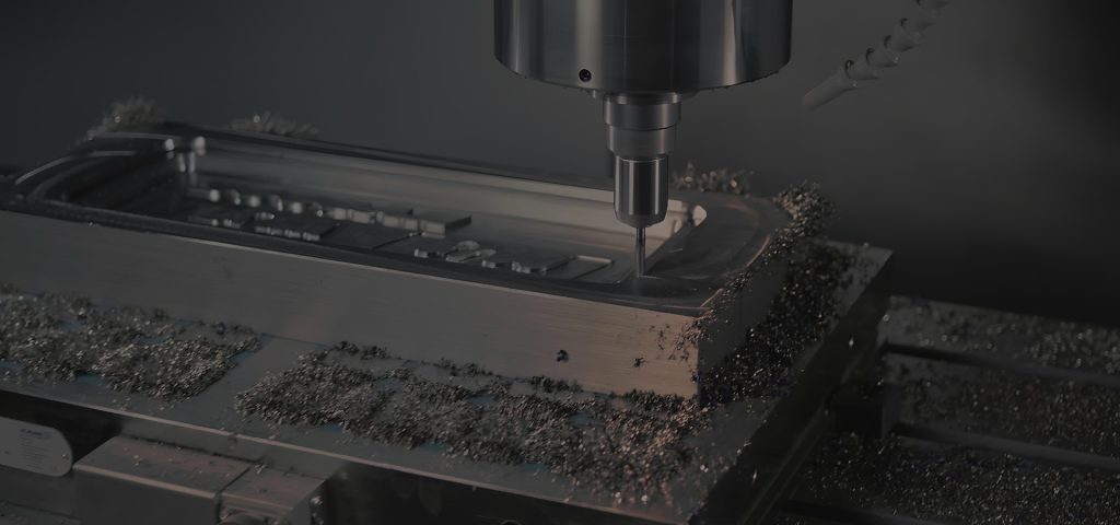
A thin floor is the same problem in another orientation. Pocketing a 6 mm plate to 1.0 mm remaining is thin-wall machining of the floor. Cutter push on the last pass dishes the floor. Anodize then freezes the dish. Call leftover thickness and which side is cosmetic.
Minimum wall, height, and ribs
Use the table as a planning start, not a guarantee. Geometry, alloy, and cosmetic class still win.
| Wall (6061-T6) | Unsupported height | Typical risk | Best for | Watch-out |
|---|---|---|---|---|
| ≥1.5 mm | ≤15 mm | Low | Standard housings | Still add radii at the floor |
| 1.0-1.2 mm | ≤12 mm | Moderate | Weight-sensitive covers | Support or leave tabs if the span is wide |
| 0.8 mm | ≤8 mm | High | Local windows, not whole boxes | Chatter, taper, anodize show-through |
| 0.5-0.7 mm | ≤5 mm | Special | Small pockets, 5-axis access | Extra ops, extra inspection, extra scrap risk |
Bottom line: keep most of the part at ≥1.0 mm and treat anything under 0.8 mm as a local feature with support, not as the default wall.
Ribs should be at least as thick as the wall they stiffen, or they become another thin wall. Fillets at the floor (1.5-3 mm) beat a sharp inside corner that a finishing mill cannot reach. A 0.2 mm CAD radius in a 12 mm deep pocket forces a tiny tool with long stick-out, which is how 1.0 mm walls go tapered.
If weight is the driver, thin in zones. Keep a 2 mm frame, drop floors to 1.2 mm, and cut 0.8 mm only where a window or a connector clearance needs it. A uniform 0.6 mm box looks light in CAD and expensive in CAM.
Height-to-thickness is the ratio that predicts chatter. Above about 10:1, plan ribs, a shorter tool, or a thicker wall. A 1.0 mm wall at 8 mm height is often fine. The same 1.0 mm at 20 mm height is a different quote.
Fixturing, chatter, and tool reach
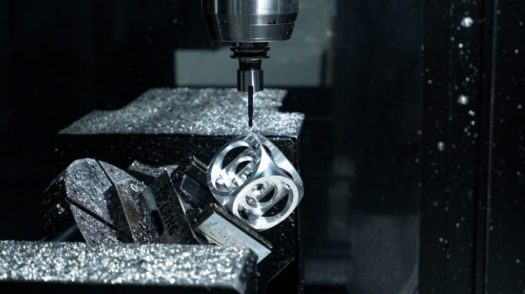
Chatter on thin aluminum is the wall moving at the cutter frequency. You hear it, then you see a wavy Ra, then anodize makes the waves cosmetic. Fix it with support, a shorter tool, a smaller step-down, or a thicker wall. Do not fix it with “machine slower” as the only instruction on the RFQ. A slow long tool still bends. A 6-8 mm mill with 1.5-3 mm floor radii and a nest under the wall is the usual fix on 1.0 mm 6061.
If the pocket is deeper than about 3× the cutter diameter, expect taper. Split the pocket, open the radius, or tilt on 5-axis so stick-out drops. Write which faces are cosmetic so the shop does not chase a wavy inside wall that the customer will never see.
Fixturing: rest the thin face on a custom nest, a vacuum plate, or sacrificial ribs you mill off later. A standard vise on two far bosses lets the center of a 0.8 mm lid flutter. If the A-side is cosmetic, say which faces can take clamp marks. Tabs you leave at 3-4 mm and mill off after unclamping are a valid process if the drawing allows them.
Tool reach: a long 4 mm mill in a 25 mm pocket will taper the wall even if the program says 0.80 mm. Allow a larger cutter or accept a thickness map. If wall thickness is contractual, name a micrometer or ultrasonic check on named points. A corner reading after Type II dye is not a map.
5-axis CNC machining can shorten stick-out by tilting into a pocket. It does not replace a rib. CNC milling of a thin box is a different fixture from a simple 3-axis plate. Say which you designed.
Internal corners still need a real mill diameter. Open floors to 1.5-3 mm radii so the finishing tool is stiff. A sharp corner plus a thin wall is two problems stacked.
Finish, residual stress, and anodize on thin walls
Milling a deep pocket in 6061-T6 plate releases mill residual stress. The part can banana when you unclamp. 7075 is often worse. Order stress-relieved plate if the lid is wide and thin, or machine in two ops with a flip and a skim. Put a flatness callout only where the gasket lives, and give a datum scheme ASME Y14.5-2018 (reaffirmed 2024) can inspect.
Anodize Type II at 8-20 µm (inside the MIL-A-8625 Type II window of 1.8-25.4 µm) is usually survivable on 1.0 mm 6061 walls. Type III at 25-50 µm (inside 12.7-114 µm, 50.8 µm if you leave thickness blank) is a larger dimensional and thermal cycle. Thin walls can oil-can in the bath or in rinses. A 50.8 µm Type III nominal on a 0.7 mm web is a process experiment, not a default.
Masked islands on a 0.6 mm web are hard to tape without collapsing the wall. If you need grounding pads, put them on a boss, not in the middle of a membrane. Use 6-10 mm pads when possible (6-8 mm is a common tape size). Sub-3 mm pads on thin skins fail by wrinkle and dye bleed. Keep rack clips off the thin A-side.
Prep: bead blast can push a thin wall. If cosmetics need blast, say the max pressure class or approve a sample. As-machined thin walls show every witness line. Type II dye will not hide chatter. Type III will freeze it.
Coordinate coating with anodizing finishing services so rack points are not parked on the thin A-side. MIL-A-8625F (2003, validation notice 2019) gives the Type II / Type III windows. You still have to decide whether the wall can take the film.
| Finish | Typical thickness | Thin-wall note | Best for | Watch-out |
|---|---|---|---|---|
| Type II Class 2 | 8-20 µm | Usual on 1.0 mm 6061 | Colored housings | Blast pressure on membranes |
| Type III Class 1 | 25-50 µm | Prefer ≥1.5 mm or local wear | Slides, rails | 50.8 µm blank on 0.8 mm lids |
| Masked ground pad | 0 µm on pad | Boss, 6-10 mm | Earth path | Tape on 0.6 mm skin |
| Conversion on pad | Thin chem film | After mask | Humid cabinets | Mixing notes with anodize |
Bottom line: pick Type II on thin cosmetics, put masks on bosses, and inspect walls after coating if thickness is contractual.
How to spec aluminum CNC thin wall machining on the drawing
How to spec aluminum CNC thin wall machining on the drawing is a short note plus a thickness map.
Write: alloy/temper, min wall, max wall if you care about weight, which walls are cosmetic, flatness on gasket faces, and post-anodize yes/no. Add a section view at the thinnest web. If you mill from both sides, show leftover floor thickness. Name Type II or Type III, Class, thickness, mask pads, and rack-OK.
RFQ pack: STEP + PDF, quantity, whether sacrificial tabs are allowed, and whether a first-article wall map is required. Say which faces can take fixture marks.
Worked RFQ example: 6061-T6 enclosure, 140 × 90 × 32 mm, 1.0 mm side walls, 1.2 mm lid, local 0.8 mm window 12 × 8 mm, internal R2, Type II Class 2 black 8-20 µm sealed, bead blast light, M3 bosses 6 mm tall, earth pad 8 mm on an internal boss (not on the 1.0 mm wall), H7 dowels masked, rack-OK on boss underside. Max unsupported wall height 12 mm. Inspect walls at points A-H after coating. Quantity 20. Tabs at the lid lip allowed if milled flush before blast.
That pack is a thin-wall job a shop can plan. The wrong pack is 0.5 mm everywhere, Type III, “anodize black,” and no fixture note.
Add a thickness map legend: points A-H on a 2D view, target 1.00 mm, after Type II, micrometer or ultrasonic. If a local window is 0.80 mm, give it its own point. If you mill from both sides, show floor thickness on the same view. First article should attach the map so lot 2 is not a photo argument.
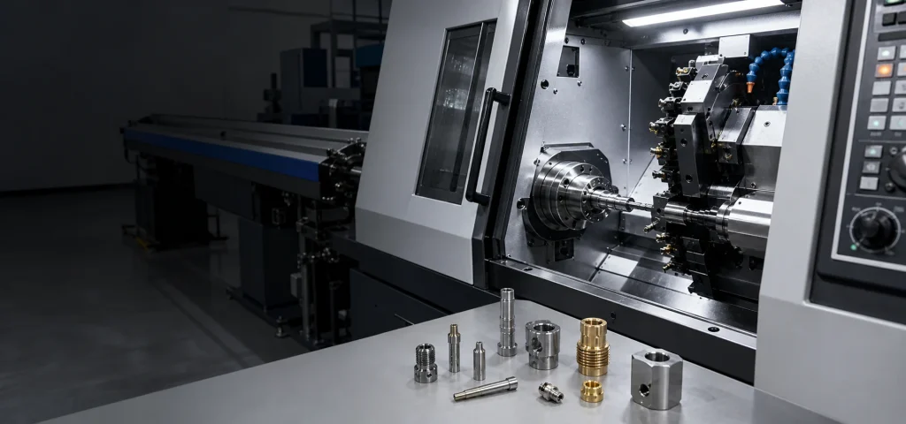
When the notes are on the PDF, send the pack through YXT CNC contact. Small-batch CNC machining is the right frame while you still change wall thickness between spins.
Process notes that belong on the RFQ, not in a chat
Tell the shop if a second finishing pass after unclamp is mandatory. Thin lids often need a skim once residual stress has moved the floor. If that skim is required to hit flatness, write it. If tabs are forbidden because the A-side cannot be touched, write that too, and expect a nest.
Tell the shop the cosmetic class of each thin face. A 1.0 mm wall that is inside the box can show witness lines. The same wall on the A-side cannot. Type II Class 2 will make that distinction expensive if you stay silent.
Tell the shop the anodize rack plan in one line: internal boss OK, thin lid not OK. A clip on a 0.8 mm lid leaves a mark and can dent the skin.
Do not ask the mill to “hold 0.80 ±0.05 mm” on a 25 mm tall web with a 4 mm tool and then Type III the part. Change one of: wall, height, tool access, or coating.
Two-side milling is a common way 1.0 mm floors fail. If you pocket a 6 mm 6061 plate from both sides, each CAM depth has tool push and a rest-material error. Call leftover floor thickness on a section and which side is datum. Leave a 1.5-2.0 mm frame so the floor is not the only stiffness in the plate. If the floor is cosmetic Type II Class 2, do not blast it at the same pressure you use on a 3 mm lid.
Masking on thin parts needs a boss. A 6-10 mm earth pad belongs on a 2-3 mm boss, not on the 0.8 mm window. Tape on a membrane leaves a wrinkle that dye will show. Type III at 25-50 µm on that same window is a bath experiment. Keep Type II 8-20 µm on the skin, Type III on a thicker rail if wear is local, and hatch pads where a fixture can reach.
If you mill Swiss-turned pins that press into the thin box, the housing still owns the anodize note. The pin drawing should say whether it is coated. Mixed documents are how a coated pin goes into a masked H7 and will not assemble.
FAQ
What is the minimum wall for aluminum CNC thin wall machining?
There is no single minimum. 1.0 mm is a common production target on 6061. 0.8 mm is frequent with support. 0.5-0.7 mm is a local special. Call min wall and max unsupported height. A 1.5 mm wall of moderate height is routine and should be your default until weight is proven. Shops can cut thinner. Holding thickness, flatness, and Type II cosmetics at the same time is the real limit.
Is 7075 better for thin walls because it is stronger?
Not automatically. Plate stress and chatter still rule. Many thin covers machine more calmly in 6061-T6. 7075 is stronger and stiffer, and pocketed plate still bananas. If you need 7075 for load, order stress-relieved stock when the lid is wide, and inspect a wall map. Do not pick 7075 to “make 0.6 mm walls safer.” Geometry and fixture still win.
Can you hold ±0.05 mm on a 0.8 mm wall?
On a short, supported web, often yes. On a tall span, put the tight tolerance on a boss or a datumed edge. Cutter deflection tapers the wall. A single corner micrometer reading will not represent the pocket center. If ±0.05 mm is contractual, name points and say after coating or before. Type III growth of 10-25 µm per surface will eat a tight wall callout that was written as-machined.
Will Type III hardcoat warp a thin housing?
It can. Prefer Type II on thin cosmetics, or add thickness before you pick Type III. Type II at 8-20 µm is the usual 1.0 mm 6061 path. Type III at 25-50 µm (or 50.8 µm if thickness is blank) is a bigger bath cycle. Oil-canning shows up after rinse and dry. If wear is local, Type III only the rail and keep the skin Type II, or leave the skin thicker.
Should I leave extra stock on thin walls for finishing?
Sometimes, as a second pass after unclamping. Note the strategy if it is mandatory. A 0.2 mm finish pass after the part is nested can recover flatness that a heavy roughing pass destroyed. Do not leave mystery stock and hope. Write remaining thickness after rough and after finish if the wall is under 1.0 mm and cosmetic. Say whether that remaining thickness is before or after Type II 8-20 µm.
Do I need 5-axis for thin walls?
Only if tool access would force a long tool on 3-axis. Many thin boxes are 3-axis with a good nest. 5-axis helps when a pocket is deep and you need a short cutter to protect a 1.0 mm wall. It does not replace ribs and it does not make 0.4 mm skins routine. Call 5-axis for access, not as a substitute for DFM.
How should I inspect thin walls?
Map thickness at named points. A single corner micrometer reading does not represent the pocket center. Use a micrometer, ultrasonic gauge, or CMM section, and say whether the reading is after Type II or Type III. Include the local 0.8 mm window and the 1.0 mm field. First article should record the map so lot 2 has a numeric target, not a photo of a “good” lid.
If aluminum CNC thin wall machining is on your housing, write min wall, height, fixture notes, Type II/III thickness, and mask pad location on the PDF, then send STEP + PDF to YXT CNC. Keep most walls at 1.0 mm or thicker. Treat sub-0.8 mm as a local, supported feature.