Choose 5-axis simultaneous vs 3+2 machining by asking whether the cutter must tilt while it is still in the cut. Simultaneous 5-axis moves X, Y, and Z together with two rotary axes, which is the usual route for sculpted walls, constant-scallop finishing, and undercuts that change tool orientation mid-pass. 3+2 machining (indexed 5-axis) locks the rotary axes, then runs a conventional 3-axis path. That is the usual route for prismatic housings, compound-angle holes, and multi-face pockets that only need a new approach direction. Keep general sizes on ISO 2768-m unless the drawing is tighter, and put ASME Y14.5 datums on the faces that must stay related. Send a STEP model plus a PDF so the shop can pick indexed work first and reserve continuous tilt for the surfaces that actually need it.
If you are a US or EU engineer sending an RFQ to a Dongguan shop, this choice is a process call, not a machine-badge call. Both modes can run on the same 5-axis mill. The quote changes because CAM time, collision checking, and rotary motion during the cut are not the same job.
Name the motion you need. A shop quoting 5-axis CNC machining services can then price a locked-tilt 3+2 route instead of a full simultaneous program you did not ask for.
Key takeaways
- Default to 3+2 when faces are planar or prismatic and you only need a new tool approach.
- Spec simultaneous 5-axis only where the tool vector must change during the cut.
- Datum control is the real gain on both modes: fewer re-clamps, not a magic tighter mill.
- Write the mode on the RFQ. If you stay silent, the shop may program the slower continuous path.
- Count setups and tool stickout on a pose list before you pay for live rotary interpolation.
5-axis simultaneous vs 3+2 machining at a glance
Simultaneous 5-axis and 3+2 are both 5-axis strategies. The difference is whether the rotary axes move while the end mill is cutting, or only between 3-axis operations.
| Factor | Simultaneous 5-axis | 3+2 indexed | Best for | Watch-out |
|---|---|---|---|---|
| Rotary motion during cut | Yes, all five axes can interpolate | No, rotary axes lock, then 3-axis cutting | Sculpted walls, blending, changing undercuts | Longer CAM, tighter collision control |
| Typical geometry | Freeform, constant tool tilt, blades that need live lead angle (ask if the shop supports that class) | Multi-face blocks, angled holes, pocketed housings | Prismatic parts that need several approaches | Does not replace a true continuous surface path |
| Datum risk | One setup can hold related faces and a sculpted wall | One setup can hold related planar faces and holes | Assembly datums across several faces | Bad workholding still stacks error |
| Quote driver | Programming + rotary feed while cutting | Index moves + standard 3-axis cycles | Lower cost when indexing is enough | Calling everything “5-axis” hides this split |
| Typical setup count | 1 fixture, live tilt on tagged faces | 1 fixture, 4–8 locked poses | Mixed covers and housings | Extra vises appear if a pose collides |
| Tool stickout | Short tool follows the wall | Short tool after the face is presented | Deep pockets, 8–12 mm cutters | A locked pose that still needs 6×D is not a win |
Bottom line: pick 3+2 as the default 5-axis plan, and add simultaneous toolpaths only on the surfaces that fail without live tilt.
What simultaneous 5-axis actually moves
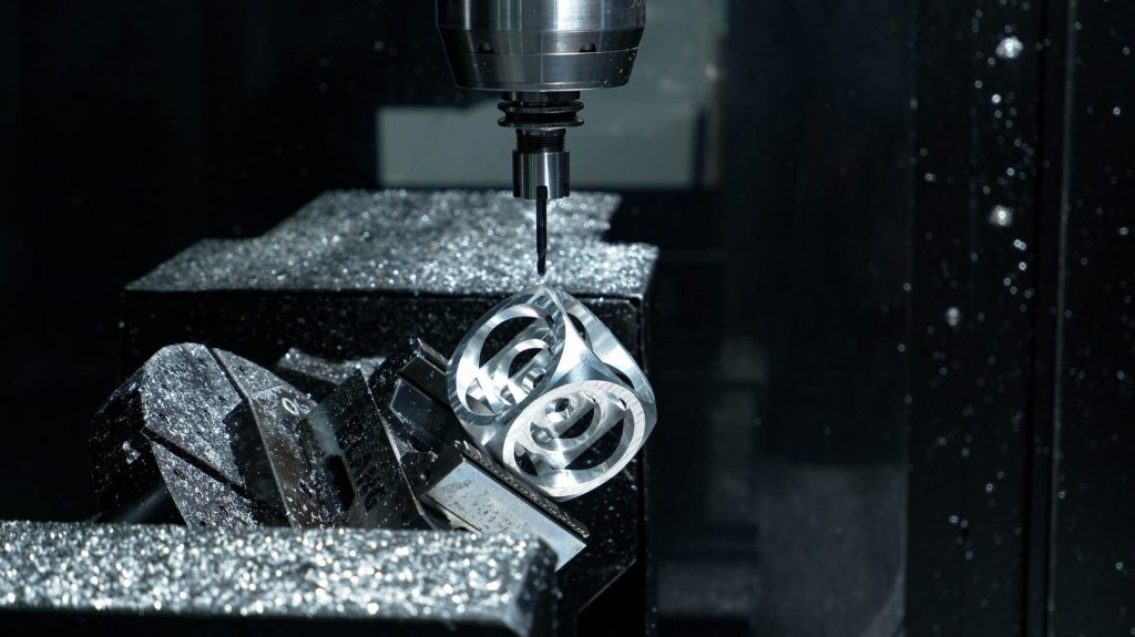
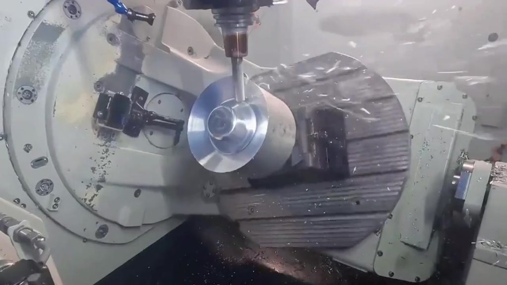
Simultaneous 5-axis means the tool or the table changes orientation while the flute is removing metal. The CAM system interpolates linear and rotary axes so the tool can stay short, hold a lead or lean angle, and keep a more even scallop on a curved wall.
That motion is useful when a 12 mm ball mill must stay normal to a blended cover, or when a 6 mm end mill has to roll under a lip that 3+2 cannot reach from a single locked pose. An angled hole at 22 degrees is a positioning problem, not a continuous-tilt problem.
Live tilt also changes feed logic. Rotary axes often run slower than X-Y-Z on the finish pass. Collision checking has to include the holder, the collet nut, and the trunnion at every point along the path, not only at the start of an operation. That is why a simultaneous finish on one pocket can cost more CAM hours than indexing six prismatic faces.
Do not use simultaneous motion to chase a size that a boring bar already holds. Feature size, tool stickout, and the gauge still govern that call. If a Ø16 H7 bore sits on a planar wall you can present to the spindle, index to that wall and bore it in 3-axis. Live rotary interpolation does not replace a stable tool and a matching plug or CMM strategy.
Ask the shop whether they support the geometry class you actually have. Sculpted consumer covers and blended fillets are common 5-axis work. Impeller-style blades and medical bone screws are a different class. Do not assume every 5-axis mill on the floor is programmed for that work. Tag the faces and ask.
What 3+2 (indexed) machining actually does
3+2 machining uses the two rotary axes as a programmable vise. The machine tilts to a pose, clamps that pose, then mills with X, Y, and Z like a 3-axis job. After the face or hole group is done, it indexes to the next pose.
This is the practical method for a 6061-T6 controller box with five exterior faces, a few M3 holes on a 15 degree face, and pockets that a 8 mm end mill can reach once the floor is presented to the spindle. You still get one fixture and one datum scheme. You do not pay for a fully interpolated 5-axis finish pass on walls that a flat end mill already cuts well at Ra 3.2.
If you already run CNC milling on 3-axis equipment, 3+2 is the same cutting physics with fewer clamps. The rotary table is doing fixture work that a second vise and a sine plate used to do.
A useful pose list is short and named by the feature, not by machine letter codes the shop may remap. Example for a 120 × 80 × 32 mm 7075-T6 cover (datum A = lid face, B = long wall, C = short wall):
| Pose | Feature group | Typical tilt intent | Tool idea | Stickout target | Done check |
|---|---|---|---|---|---|
| P1 | Datum A face mill, lid screw pockets | Table flat, B0 C0 | 12 mm face mill, then 8 mm EM | L/D ≤ 3 | Floor flat, pockets to depth |
| P2 | Datum B wall, cable-gland boss | Present wall to spindle | 8 mm EM, 6 mm drill | L/D ≤ 4 | Boss height and hole axis |
| P3 | Datum C wall, USB window | Present short wall | 6 mm EM | L/D ≤ 4 | Window size, no witness step |
| P4 | 18° connector face, 4× Ø3.4 holes | Lock compound angle | 3.3 mm drill, 90° spot | Stickout just past breakout | Hole axis to A-B-C |
| P5 | Opposite wall, M4 threads | 90° from P2 | 3.3 mm drill, M4 tap | Standard tap stickout | Thread depth from start face |
| P6 | Sculpted inner blend (only if P1–P5 cannot see it) | Live tilt, not a locked pose | 6–8 mm ball mill | Short as the blend allows | Scallop and blend radius |
Poses P1–P5 are 3+2. P6 is simultaneous, and only if a locked pose still leaves a shadowed fillet. If P6 is empty, the whole job is indexed.
Setup count for that cover: one soft jaw, one stock, six programmed poses, zero re-clamps for the datum frame. A 3-axis plan for the same part is often five vises (A, B, C, compound face, opposite wall). Each vise is a new alignment. That is the 5-axis value even when rotary axes never move in the cut.
When 5-axis simultaneous vs 3+2 machining changes the quote
5-axis simultaneous vs 3+2 machining changes the quote when CAM hours, prove-out, and in-cut rotary time show up as real cost, not when the machine label says “5-axis.” A 3+2 program is often a set of 3-axis operations with a short index list. A simultaneous program needs tool-axis control, more collision checking, and slower rotary feeds on the finish pass.
Ask the shop to split the estimate: indexed faces versus continuous surfaces. On mixed parts, a hybrid is normal. Rough and square the prismatic body in 3+2, then run a simultaneous finish only on the sculpted pocket. That split is usually cheaper than forcing the whole body through live 5-axis motion.
Do not use simultaneous 5-axis as a way to chase ±0.005 mm on a simple bore. Feature size, tool stickout, and inspection method still govern that call. General sizes can stay on ISO 2768-1 (1989) medium unless the fit needs a tighter note.
Tool stickout is the other quote lever. A 40 mm deep pocket cut with an 8 mm end mill from a 3-axis vise is a 5×D stickout before you add holder clearance. Deflection shows up as tapered walls and a stepped floor. Indexing the housing so a 10 mm end mill reaches the floor at about 3×D is often a 3+2 move. Simultaneous tilt is the next step only if the wall itself is curved and the short tool must lean while it climbs.
If the part is aluminum, call the temper. Aluminum CNC machining on 6061-T6 forgives a slightly long tool more than 7075-T6. Harder 7075 tells you faster when stickout is wrong. That material note belongs on the PDF beside the motion note.
Worked RFQ: mixed cover, 20 pieces
Here is a packet you can copy. It is one decision: 3+2 default, simultaneous only on the tagged blend.
Part: instrument cover, 7075-T6, 120 × 80 × 32 mm, qty 20, as-machined Ra 3.2, no anodize on this lot.
Datums: A = outer lid face, B = long side, C = short side. Lid screw true position Ø0.15 mm to A-B-C. Four connector holes on an 18° face, true position Ø0.20 mm to A-B-C.
3-axis sketch (rejected): five vises. Vise 1 mills A and pockets. Vise 2 mills B. Vise 3 mills C. Vise 4 needs a sine block for 18°. Vise 5 mills the opposite wall. The connector true position would restack after vise 4. Setup count: 5. Longest tool: 8 mm EM at ~42 mm stickout in the board pocket.
5-axis plan (accepted): one vise on a trunnion. Pose list P1–P5 as in the table above. Board pocket is presented in P1 so a 10 mm EM finishes the floor at ~28 mm stickout (L/D about 2.8). Connector holes in P4 with the rotary locked. Sculpted inner blend tagged 5AX-CONT because no locked pose sees the full R6 fillet under the lip.
Motion note on the PDF: “Prefer 3+2. Simultaneous only on surfaces tagged 5AX-CONT. Rotary locked during cut on all other faces.”
Inspection: CMM on A-B-C, lid pattern, and the four connector holes. Calipers on ISO 2768-m sizes. First article on the first piece, then a sampling plan you name.
Files: STEP and PDF at the same revision. Highlight the 18° face and the 5AX-CONT fillet in a contrasting color.
That packet lets a Dongguan programmer price indexed hours for P1–P5 and a smaller simultaneous block for one fillet. If you only write “full 5-axis,” P1–P5 may be programmed as live tilt for no functional gain.
ASME Y14.5 (2018) is what makes the true-position lines real. If you omit the datum frame, the shop cannot tell that vise 4 was the reason you bought 5-axis.
Decision tree for your RFQ
Walk the model once and lock the mode before you ask for a number.
- If every machined face is reachable with 3-axis vises and the datum stack is loose, quote 3-axis first.
- If several faces share a tight positional callout (true position to datum A-B-C) and extra clamps would break that stack, quote 5-axis, then choose the mode below.
- If the cutter only needs a new approach (angled holes, face milling a compound plane, pocketing after a tilt), specify 3+2.
- If the cutter must change orientation during the pass (sculpted wall, constant-scallop blend, undercut that no single pose can see), specify simultaneous 5-axis on those faces only.
- If a locked pose still needs more than about 5×D stickout on the finishing tool, change the pose, open the fillet, or split the pocket before you add live tilt.
- If you are unsure, mark the sculpted faces and tell the shop: “3+2 default, simultaneous only where indexed access fails.”
That is a decision, not a shrug. Prismatic product housings land on step 3 most of the time. Blended covers land on step 4 for the blend only.
ASME Y14.5 (2018) is the language for the datum frame that makes step 2 real. If you only show plus-minus sizes, the shop cannot tell which faces must stay in one setup. Write the mode on the PDF: “Prefer 3+2. Simultaneous only on surfaces tagged 5AX-CONT.” NIST manufacturing pages still treat measurement method as part of the requirement, which is how 2026 RFQ reviews should treat CMM versus caliper features (NIST).
When the packet is ready, contact YXT CNC with STEP, PDF, and that motion note. If the cover is still a prototype quantity, keep the same motion split on later lots until the blend disappears. For small-batch CNC machining, a frozen pose list is cheaper than a new simultaneous program every revision.
FAQ
Is 3+2 machining the same as 5-axis?
Yes, 3+2 is a 5-axis machine strategy, not a different machine class. The rotary axes position the part, then cutting is 3-axis. Simultaneous 5-axis keeps those rotary axes moving in the cut. Your RFQ should name the strategy because both can appear on the same mill. If the quote only says “5-axis,” ask whether rotary axes lock between operations. That answer is the cost split.
Does simultaneous 5-axis always hold tighter tolerance than 3+2?
No. Setup count and datum control usually matter more than live rotary interpolation. A short 3+2 tool on a locked pose can beat a long simultaneous tool on a weak stickout. Tight bores still want a boring cycle, a reamer, or a gauge that matches the fit. Live tilt helps when the wall is sculpted or the tool must lean to stay short. It does not replace ISO 2768-m on general sizes or a datum frame on the faces you will CMM.
Can one part use both 3+2 and simultaneous toolpaths?
Yes. Hybrid programs are common: index for prismatic faces, then run continuous tilt on the sculpted region. Ask the shop to show which faces use which mode. On the cover example, P1–P5 stay locked and only the tagged fillet interpolates. That split keeps CAM hours on the surface that needs them. If the shop cannot show the split, assume they priced live tilt on walls a flat mill already finishes after an index.
Do I need simultaneous 5-axis for compound-angle holes?
No. Compound-angle holes are a positioning job. 3+2 (or a dedicated drill fixture) can present the hole axis to the spindle, then drill or mill in 3-axis. Put the compound angle on a true-position view, not only in a 3D screenshot. Give the start face and the breakout face so stickout is planned. A Ø6.6 hole at 22 degrees with true position to A-B-C is an indexed pose, not a sculpted path.
Should I put “full 5-axis” on every complex RFQ?
No. “Full 5-axis” often gets programmed as simultaneous by default. Name 3+2 unless a surface fails without live tilt. Attach a pose list even if the shop remaps B and C to their table. The list is a feature-access document. It stops the programmer from interpolating rotary axes on a pocket floor that P1 already presents to the spindle. If you cannot list poses yet, list faces and say “locked approach per face.” That is still better than “full 5-axis,” which reads as simultaneous to many CAM seats.
Does ISO 2768-m decide the machining mode?
No. ISO 2768-1 (1989) only sets general size and geometry grades when you do not give a tighter spec. Mode selection still follows tool access and datum stack. A loose general tolerance can still need 5-axis if four faces share a true-position frame. A tight bore on one 3-axis face does not need simultaneous tilt. Keep the standard on unmarked sizes, then pick the mode from the pose list.
How many setups should a 3+2 job have compared with 3-axis?
Often one fixture versus four or five vises on a multi-face cover. Count the orientations a 3-axis mill would need, then ask whether those orientations share a datum frame. If they do, one 5-axis setup with a pose list is the usual win. If they do not, 3-axis with two vises may still be cheaper. Setup count is the comparison, not the word “5-axis.”
Put the decision on the drawing: 3+2 unless the cutter must tilt in the cut. If you want a Dongguan process review of 5-axis simultaneous vs 3+2 machining, send STEP, PDF, the pose list, and the tagged faces through the 5-axis CNC machining services page or the contact form.