CNC internal corner radius design is how a pocket turns a corner so an end mill can reach the wall, chips can leave, and the part does not crack at a sharp notch. A mill cannot cut a true sharp inside corner. It leaves a radius at least as large as the tool, and a long stick-out in a deep 6061-T6 or 7075-T6 pocket will chatter before it finishes a tiny R0.2. Size the corner for access and stress first: open the radius, add a corner relief or dogbone when a square insert must seat, or call wire EDM only where the function forbids a fillet. Put the radius on the PDF, not only in the STEP.
If you send an RFQ from the US or EU with dead-sharp pocket corners, a Dongguan programmer will leave stock, use a tiny tool that sings, or quote EDM. None of those is what you sketched in CAD.
This guide is not a mill-diameter catalog. The decision is how the corner behaves in the pocket: tool reach, leftover stock, and stress, plus whether a mating part needs a square seat.
Key takeaways
- Sharp internal corners are a process change (tiny tool, leftover radius, or EDM), not a free CAD click.
- Open the radius until the tool can finish the wall at a stick-out the pocket depth allows.
- Use a dogbone or corner relief when a square insert must sit flat.
- Call the radius on the drawing. A model-only fillet is easy to miss in CAM.
What CNC internal corner radius design controls
CNC internal corner radius design controls three things at once: whether the cutter can finish the wall, how much uncut stock stays in the corner, and how peaked the stress is when the pocket is loaded.
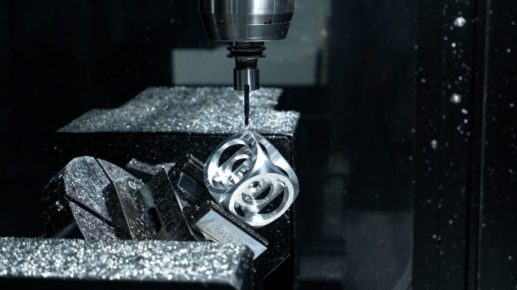
A rotating tool is a cylinder. At the inside corner it traces its own radius. If you drew R0, the shop still has to leave a fillet, switch to a needle mill, or burn the corner.
Deep pockets make this worse. Long, thin tools deflect. The wall looks good in the middle and heavy in the corner. That is an access problem, not a mill-size table problem.
Rule of thumb for 3-axis CNC milling: the finishing mill diameter is about twice the corner radius you dimension (an R2 corner wants a Ø4 mm mill, plus a little clearance if you want the mill to keep moving). Pocket depth then sets stick-out. A Ø4 mm mill at 12 mm stick-out in 6061-T6 is often fine. The same Ø4 mm mill at 35 mm stick-out will leave a fat corner or a chatter mark. Opening the radius to R3 or R4 lets you step up to a Ø6-Ø8 mm mill and shorten the drama.
If the pocket is a datum feature (for example datum A is the pocket floor, or a wall is datum B), leftover corner stock also wrecks inspection. A CMM that is supposed to hit a plane will hit the fillet instead, or the operator will pick points away from the corner and you will argue about which plane is real. Treat the radius as part of the datum definition when the pocket locates the assembly.
NIST manufacturing pages (2026) will not pick your radius for you. They will treat the named process as part of the spec. If the print says mill and the corner says R0, the spec is already in conflict.
Pocket corners, tool access, and leftover stock
Pocket depth sets how long the tool must hang out. The longer the stick-out, the more the corner wants a larger radius so you can use a stiffer mill and still finish the wall.
A 12 mm-deep pocket with R0.3 corners in 6061-T6 is a chatter bet. The same pocket with R2 or R3 lets a stronger tool finish the wall. You still specify the radius the function needs.
If the pocket is deeper than a 3-axis stick-out can hold, 5-axis CNC machining can shorten the tool by tilting. That is still a corner-access choice. Tilting does not create a sharp inside corner. It only lets a larger mill reach a wall that a long 3-axis tool could not finish.
Uncut stock is the silent killer of fit. The wall mics in spec. The square insert hits the leftover radius and sits high. Catch that with a larger fillet or a relief.
Worked RFQ pocket. Housing in 6061-T6, pocket 40 x 30 x 12 mm, originally modeled with R0.2 in every corner so a 20 x 20 x 8 mm square carbide insert would “sit in the corner.” The insert does not sit in the mill radius. It hits the fillet and stands 0.3-0.6 mm high. Fix: open three corners to R2.5, and put a dogbone (or a Ø6 mm drilled relief) in the two corners where the insert must reach the wall. Call pocket depth 12.2 mm full, floor Ra 3.2. On the ballooned FAI, inspect wall straightness on the land, not inside the dogbone.
When you send the RFQ, mark pocket depth, corner radius, and whether a mating block must sit to the corner. That one note changes the quote more than a generic “high precision” line.
Access checklist before you export STEP:
- For each internal corner, write the radius on the PDF.
- Compare radius to pocket depth. If depth is more than about 3-4 times the mill diameter implied by the radius, expect chatter or leftover stock.
- If a square insert, gasket, or stamped stack needs a sharp seat, add a dogbone or undercut. Do not leave R0 and hope.
- If anodize is Type II 5-25 µm, remember coating builds in corners. A tight R0.5 can close up.
- If the corner is on a datum wall, say whether the inspector may ignore a stated distance from the fillet.
Stress at internal corners vs a sharp CAD model
A sharp inside corner is a notch. Under clamp load, press fit, or cyclic load, that notch is where 7075-T6 and even 6061-T6 like to start a crack.
The Aluminum Association alloy pages (2026 listings) describe 6061-T6 and 7075-T6 as heat-treated grades. Neither wants a knife-edge inside a loaded pocket. Opening the radius spreads the stress. Put R1-R3 on a housing rib when the assembly allows it.
If the corner is only cosmetic, still avoid R0. Anodize pulls away from a knife edge, and handling dings show there first.
Call the radius as a real dimension, the way ASME Y14.5-2018 treats specified geometry. “Break sharp edges” is an external-edge note, not a pocket-corner spec. Break-edge notes usually mean 0.1-0.5 mm on outside edges. They do not authorize a mill to leave R1.5 in a pocket you modeled sharp, and they do not authorize a needle mill to chase R0.1 in a 20 mm-deep pocket.
Stress and tool access often agree. The radius that lets a Ø6 mm mill finish a 10 mm-deep pocket is also kinder in fatigue than R0.2. When they fight (a square hydraulic spool land, a semiconductor nest), use a local relief so the loaded wall still has a radius in the unused corner.
Do not specify a tiny radius and a tight profile on the same wall without a method. Profile 0.05 mm on a chattering needle mill will fail FAI even if the CAD looks crisp. Either open the radius or call EDM on that feature.
When to use a dogbone, a relief, or EDM
Some assemblies need a square seat: a gasket pocket, a carbide insert, a stamped stack. A generous fillet then fights the function. The fix is a local relief, not a global sharp corner.
A dogbone or corner undercut lets the mill swing through the corner so the walls can be square where the insert lands. You keep tool access and a radius in the relief. Typical dogbone: drill or mill a Ø equal to about 1.2-1.5 times the finishing mill, centered on the sharp corner, deep enough to clear the insert thickness. Keep the scallop outside the land. Show the dogbone on the drawing. A model-only undercut is easy to delete as “tooling body.”
Wire EDM is the remaining path when the corner must be sharp and the relief is forbidden. Call EDM on that feature. Do not hope milling will “get close.” Recast layer, extra op, and longer lead are part of that choice. If only two corners on a large plate need EDM, say so. Do not EDM the whole pocket because two corners are R0.
Corner process table (use with the access checklist above):
| Corner choice | Tool access | Stress | Square insert fit | Watch-out |
|---|---|---|---|---|
| Dead-sharp (R0) | Poor unless EDM or a needle mill | Worst notch | Looks right in CAD | Leftover mill radius or chatter |
| Generous milled radius | Best: shorter, stiffer tool | Best if the radius is real | Insert may hit the fillet | Must clear the mating part |
| Dogbone / corner relief | Good: mill swings through | Good inside the relief | Best for a square seat | Scallop must stay outside the land |
| Wire EDM sharp corner | N/A (different process) | Still a notch | True square possible | Recast, extra op, longer lead |
Bottom line: pick generous radius by default, relief when the seat must be square, EDM only when both of those break the function.
If the pocket also has a deep hole in the floor (sensor bore, drain), treat hole L/D as a separate callout. A Ø3 mm x 22 mm blind hole (about 7xD) in a sharp-corner pocket stacks two hard features on one toolpath. Open the corners so a decent mill can finish the pocket, then name the hole process. Do not make the same Ø2 mm mill drill the hole and try to finish R0.2 corners.
CNC internal corner radius design on the drawing
CNC internal corner radius design only reaches the machine if it is on the PDF the buyer and the shop both freeze. A fillet that lives only in the STEP is easy to delete in a “simplify for CAM” pass.
Put a note: internal pocket corners R3 unless dimensioned. Then dimension the exceptions. If anodize is Type II 5-25 µm on aluminum CNC parts, coating builds in corners. A tight R0.5 can close up after anodize.
For custom CNC machining, a DFM pass should flag every internal R smaller than the pocket depth can support. You still own the function. The shop should tell you the access and chatter risk before they cut.
Drawing notes that survive FAI:
- Default internal radius (example: R2 unless shown).
- Named exceptions with view balloons (R0.8 at the seal land, dogbone Ø6 at insert corners).
- Pocket depth as full depth, not a section that hides a step.
- Finish on the floor and walls (Ra 3.2 typical as-machined).
- Whether the corner is before or after coating.
- Datum letters if a pocket wall or floor is A, B, or C, plus a note that fillet zones are excluded from the plane.
Balloon those notes on the first article. A CMM can verify a radius with a few points or a scan. A caliper across the wall cannot. If you will not inspect the radius, do not pretend R0.2 is a functional requirement. If you will inspect it, give a tolerance (R2.5 ±0.2 mm is a millable band; R0.20 ±0.02 mm in a 15 mm-deep pocket is a fight).
Walk the pockets before you export: every internal corner has a radius or a named relief, and pocket depth is on the PDF. If a corner is still R0, you have chosen a special process. Write it down.
How pocket corners show up on ballooned FAI
Ballooned first article inspection is where a model-only fillet becomes a lot problem. If the radius is on the PDF, it gets an ID, a method, and a pass/fail. If it lives only in the STEP, CAM may keep it and the inspector may never look.
Use the same 40 x 30 x 12 mm 6061-T6 pocket from the RFQ example. Cut the first article on the production fixture. Do not FAI a hand-blended tryout that a needle mill survived once.
| Balloon | Requirement | Method | Typical fail |
|---|---|---|---|
| 20 | Internal corners R2.5 ±0.3 mm | Radius gauge or CMM scan | Leftover mill radius, or a fat corner from a dull tool |
| 21 | Dogbone Ø6 at two insert corners | CMM / caliper | Scallop eats the land |
| 22 | Land straight where the 20 x 20 insert sits | Height gauge / CMM | Insert sits 0.3-0.6 mm high |
| 23 | Pocket depth 12.2 mm full | Depth mic | Floor not reached in the corner |
| 24 | Floor Ra 3.2 | Ra tester | Bead blast that was not on the print |
Bottom line for this table: inspect the land and the named radius, not a photo of a shiny pocket.
If datum A is the pocket floor, exclude the fillet zone in the note and in the CMM program. Probing into R2.5 pulls the plane off the land. ASME Y14.5-2018 datum targets, or a simple exclusion distance, keep A on the real seat. A first article that “passes A” because the probe sat on leftover stock will miss the insert the same way a square corner miss does.
Do not wait until FAI to discover R0. Open the radius or name the relief in DFM. FAI should confirm the choice, not invent it. If balloon 20 fails because the shop used a Ø3 mm mill in a 12 mm-deep corner you called R2.5, the process is wrong. Recut with a mill that matches the radius, or change the print. Releasing the lot repeats the leftover stock.
On small lots the same rule holds. Ten pieces with square inserts fail the same way two hundred pieces fail: the wall mics in spec and the corner is fat. Balloon the corners that control fit even when the rest of the sheet is ISO 2768.
If the pocket floor also has a deep hole, keep that hole on its own balloons (size at named depths, L/D process). Do not hide a 7xD sensor bore under the same ID as R2.5. Corner radius and hole depth fail for different reasons and need different tools.
FAQ
What internal corner radius should I use on CNC pockets?
Use the largest radius the assembly allows, sized so a mill can finish the wall at that stick-out. Many housings work at R1-R3 mm. Smaller than about R0.5 in a deep pocket is a chatter risk. Match the radius to roughly half the finishing mill you want the shop to use, then check stick-out against pocket depth. If the insert or gasket needs a square seat, keep the land straight and put the radius in a dogbone, rather than shrinking every corner.
Can CNC mills cut a sharp internal corner?
No. A mill leaves a radius. Sharp inside corners need a relief, a tiny tool with leftover risk, or wire EDM. Do not dimension R0 and expect a standard end mill to match the CAD. A Ø1 mm mill in a 12 mm-deep 7075-T6 pocket will chatter or break before it copies your sharp solid. If the function is truly sharp, call EDM on that corner and keep the rest of the pocket millable.
Why do my square inserts sit high in a milled pocket?
They are hitting leftover corner radius or uncut stock. Add a dogbone or open the fillet so the land is straight where the insert sits. Measure the pocket wall in the middle, then check the insert height. If the wall is in spec and the insert is high, the corner is the problem. Balloon the land length and the relief on FAI so the shop cannot pass a pretty wall that still kills the seat.
Does a larger internal radius weaken the part?
Usually the opposite for a loaded pocket. A larger radius lowers the notch effect. Weakening comes from removing wall thickness, not from opening the corner. Keep rib thickness and floor thickness as the structural callouts. Use R1-R3 on 6061-T6 and 7075-T6 housings unless a square seat forbids it. If a FEA model assumed a sharp corner, rerun it with the mill radius. The milled part will not match the sharp CAD stress plot.
Should I put the fillet only in the 3D model?
No. Put the radius on the 2D drawing you inspect. Model-only fillets get dropped in CAM or missed on FAI. ASME Y14.5-2018 treats specified geometry as drawing requirements. A STEP fillet with no PDF dimension is a CAM suggestion. Balloon the default radius note and every exception. If the model and the drawing disagree, the shop will pick one and you will lose the first article.
When is wire EDM worth it for a pocket corner?
When the function forbids both a fillet and a relief, and you accept a second process. Call EDM on that feature so the quote is honest. Two EDM corners on an otherwise milled plate are a normal RFQ note. A whole pocket called R0 with no EDM note is a conflict. Recast, flush, and inspection of a sharp notch are part of that choice. Do not use EDM to hide a CAD habit of leaving every sketch corner sharp.
Close CNC internal corner radius design on the PDF: radius or relief, pocket depth, and whether a square seat is required. Then send the STEP and drawing for a DFM pass through the contact page before you freeze R0 in a deep pocket.