5-axis indexed machining explained in shop terms: the rotary axes move the part to a pose, lock, then the mill cuts with X, Y, and Z only. That is 3+2, not simultaneous 5-axis. Use it for compound-angle holes, multi-face pockets, and prismatic housings that need several approaches in one vise. Put ASME Y14.5 datums on the faces that must stay related, keep general sizes on ISO 2768-m, and call the tilt on the PDF (for example “index B27 C15, then drill Ø6.6”). Send STEP plus PDF so a Dongguan programmer can build the pose list. You are done specifying it when every angled feature has a locked approach and no face still needs the tool to tilt during the cut.
If you buy CNC milling from a China factory, indexed 5-axis is the mode most product parts actually need. The RFQ fails when the drawing never says “index then mill,” so CAM is written as live 5-axis motion by habit.
This how-to is the callout and pose-list method, not a comparison essay. You will leave with a PDF note a programmer can follow.
Key takeaways
- Indexed 5-axis equals lock rotary, then 3-axis cutting. The fifth axis is a programmable fixture.
- Write each tilt as a pose plus the operation that runs at that pose.
- Datums must survive the whole pose list. That is why you index instead of re-clamping.
- If a wall still needs the tool to lean during the pass, that wall is not an indexed feature.
- Prove the pose list in CAM collision check before you treat the RFQ as complete.
5-axis indexed machining explained in one setup
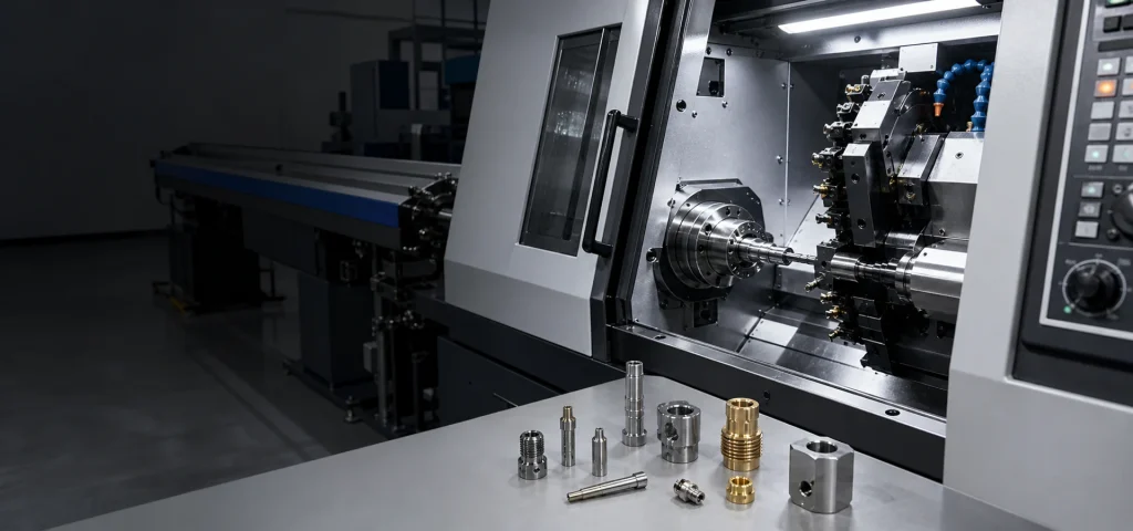
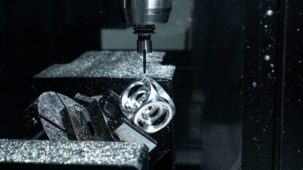
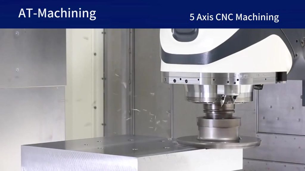
5-axis indexed machining explained on the machine looks like a vise on a trunnion or a swivel table. The control rotates the part to a stored angle, the brakes hold, and a normal 3-axis program mills the presented face. Then the table moves to the next stored angle.
That is why cycle time often looks like 3-axis plus a few seconds of index. You are not interpolating A and C through a finish pass. You are changing fixtures without opening the vise.
A typical job: 6061-T6 manifold block, datum A on the bottom, four ports at 20 degrees, one soft jaw, and an 8 mm end mill that stays short because the face comes to the spindle.
Setup count is the point of indexing. The manifold that needed four vises plus a sine plate becomes one clamp and a pose list. If indexing still needs three re-clamps, the jaws are hiding faces or the stock is wrong. Fix workholding before you add simultaneous motion. Simultaneous motion does not replace a pose that never was defined.
Name the clamp. Soft jaw on the unmachined stock, or a dovetail on the bottom, or a tombstone subplate. Indexed 5-axis fails in the quote when the buyer assumes “one setup” and the shop still needs a second op because the jaws cover datum B. Put a note: “jaws may hold leftover stock on A; all ports and the gallery must be reachable without opening the vise.” That is 5-axis indexed machining explained as workholding, not as a rotary brochure.
How indexing differs from continuous rotary cutting
Indexing holds a constant tool vector during the cut. Continuous 5-axis changes that vector while the flute is in metal. If you mix them in your head, the shop will mix them in the quote.
Use indexing when the feature is a plane, a hole axis, a pocket floor, or a boss that a flat or ball mill can finish from one direction. Use continuous motion only when no single pose can see the whole surface, or when scallop height on a blend requires a changing lead angle.
Workholding is still 3-axis thinking. The part must be clear of the trunnion, the tool must miss the vise jaws at every pose, and chip load still follows material: 6061 is not 304.
| Factor | Indexed 5-axis (3+2) | Simultaneous 5-axis | Best for | Watch-out |
|---|---|---|---|---|
| Rotary during cut | Locked | Moving | Prismatic faces, compound holes | Calling all 5-axis work “live 5-axis” |
| Tool vector | Constant per pose | Changing | Short tools, predictable scallop | A blend that no single pose can see |
| Quote risk | Lower if poses are listed | Higher CAM and collision time | Housings with 4-6 approaches | Missing a pose and forcing a second fixture |
| Inspection | Datum frame plus angled holes | Same, plus freeform surfaces | Ports and sealing faces | “Inspect everything” with no gauge |
| Stickout | Set per pose after the face is presented | Changes along the path | Deep ports, short drills | A pose that still needs 6×D |
Bottom line: if every feature has a locked approach, write indexed 5-axis on the RFQ. If a wall still needs the tool to lean during the pass, that wall is not an indexed feature.
How to mark datums and tilt angles on the drawing
The PDF has to carry the datum frame and the pose intent. ASME Y14.5 (2018) is the datum language. Plus-minus sizes alone cannot tell a programmer which faces stay in one setup.
Useful callouts:
- Datum A primary, B secondary, C tertiary, all in the same frame across poses
- Hole axis with a compound angle shown in a true-position view, not only a 3D screenshot
- Note: “5-axis indexed (3+2). Rotary axes locked during cut.”
- Optional: a table of poses (Pose 1: B0 C0 face mill datum A. Pose 2: B20 C0 drill ports.)
Keep general sizes on ISO 2768-1 (1989) medium. Put tight numbers on the port true position and the sealing face. If you tighten every wall, the indexed program gets slower without a better assembly.
NIST manufacturing measurement pages still pair the feature with the gauge method, which is the right 2026 habit for indexed holes (NIST). If the port is a pipe fit, name the gauge. If it is clearance, say clearance.
You do not have to publish machine B and C as legal dimensions. Feature angle plus a STEP is the authority. A note “shop may select table angles that present this axis to the spindle” keeps you from fighting a trunnion convention. What you must publish is the locked-mode sentence and the list of features that share the fixture.
If the manifold is aluminum, name 6061-T6 or 7075-T6. Feeds and stickout change with temper. The aluminum CNC machining page is the alloy context. The pose list is still the process spec.
Worked pose list: 6061-T6 manifold, 15 pieces
Part: 90 × 70 × 45 mm 6061-T6 manifold. Datum A = mounting floor. Four Ø8.4 ports at 20° from A on two walls. One Ø12 counterbore on A. Internal gallery pocket 28 mm deep, fillet R5. Qty 15. Ra 3.2 sealing faces. ISO 2768-m elsewhere. True position Ø0.20 mm on ports to A-B-C.
3-axis setup count (rejected): vise 1 (A and pocket), vise 2 (wall 1), vise 3 (wall 2), sine fixture for 20° ports, possible fifth op for the opposite wall. Stickout in the gallery from vise 1: 8 mm EM at ~35 mm (L/D ≈ 4.4), borderline.
Indexed plan, one soft jaw, setup count = 1:
| Pose | Feature angle intent | Operations | Tool | Stickout / L/D | Collision note |
|---|---|---|---|---|---|
| M1 | Present A to spindle | Face mill A, Ø12 C’bore | 50 mm face mill, 12 mm EM | L/D ≤ 2 | Stock extra on A for a second skim if needed |
| M2 | Tilt so gallery floor faces the spindle | Rough and finish 28 mm pocket | 10 mm EM, R5 allowed | ~30 mm, L/D ≈ 3 | Jaws below the floor, not in the pocket |
| M3 | 20° ports on wall 1 | Spot, drill Ø8.4, optional bore | 8.3 mm drill | Drill just past breakout | Drill must miss opposite wall at breakout |
| M4 | 20° ports on wall 2 | Same as M3 | Same | Same | Trunnion swing vs tall boss on A |
| M5 | Opposite wall, wrench flats | 8 mm EM | L/D ≤ 3 | Check vises at 90° | |
| M6 | (empty unless CAM shows a shadowed fillet) | Simultaneous, not indexed | Ball mill | n/a | Only if R5 undercut appears |
PDF note: “5-axis indexed (3+2). Rotary locked during cut. Feature angles govern. Shop maps B/C.” Inspection: CMM on A-B-C and four ports. Calipers on ISO 2768-m.
You are done specifying indexed machining on this RFQ when M1–M5 cover every colored face and M6 stays empty. If M6 fills, tag that fillet 5AX-CONT and keep the rest indexed.
Ask the shop to mirror the table with their machine poses. Their B and C will not match your sketch. Their feature list must. If M3 and M4 collapse into one pose because both port groups face the same way after a table map, that is a win. If they add M7 because a boss collides at M4, that is a stock or jaw change, not a reason to switch the whole job to simultaneous. Setup count should remain 1 unless they explain the extra clamp.
Procedure: 5-axis indexed machining explained on an RFQ
Follow this sequence. Each step names the tool, the spec, and the done check.
- Open the STEP and the PDF at the same revision. Confirm the filename revision matches the title block. You are done when there is no second “latest” model in the email thread.
- Highlight every face and hole that is not parallel to the primary 3-axis axes. Use a PDF markup or a colored STEP body. You are done when an uncolored angled feature no longer exists.
- Assign a locked tool approach to each highlighted feature (face mill, pocket, drill, bore). Write the approach as an index pose, not as “5-axis.” You are done when each feature has one pose and one tool idea (for example 8 mm end mill, L/D ≤ 4).
- Write the datum frame and the indexed-mode note on the PDF. Include “rotary locked during cut.” You are done when a stranger can see that 3+2 is required and simultaneous is not.
- List collisions to avoid: vise jaws, trunnion swing, a tall boss that hits the spindle at Pose 4. You are done when the tallest feature has a clearance note or a shorter stock plan.
- State inspection: CMM on the datum frame and angled holes, calipers on ISO 2768-m sizes. You are done when the RFQ does not say “inspect everything” with no method.
- Send the packet to the shop and ask them to return the pose list they will program. You are done when their list matches your highlighted features, or they mark a feature that still needs live tilt.
A common failure is step 3 written as “full 5-axis.” That is not a pose. The programmer then interpolates rotary axes on walls a 3-axis path already could cut after an index.
Stickout belongs in step 3 as a number. “Drill Ø8.4, stickout past breakout + 5 mm, L/D on the 10 mm pocket mill ≤ 3 after tilt.” If you skip the number, the shop may index to a pose that still uses a long tool, which wastes the mode. Indexing is for presenting the face. It is not automatic stiffness.
If you want that packet reviewed in Dongguan, attach it on 5-axis CNC machining services rather than sending a screenshot of the compound hole.
Common failures that make indexed programs expensive
Indexed work gets expensive when the pose list is incomplete. Watch for a boss that collides at the last tilt, a pocket that still needs 6×D stickout after the index, threads on a compound face with no start-face note, and stock that is too tall for the trunnion at 90 degrees.
Fix those on the model. If a feature cannot be reached from any locked pose, reclassify it as simultaneous or split the part.
Stock height is a setup-count problem in disguise. A 70 mm tall blank on a small trunnion may hit the spindle at Pose M4. The shop then adds a second clamp, and you have paid for 5-axis without the one-setup benefit. Put a max stock envelope on the RFQ or allow a sawn blank that is closer to 50 mm.
Holder collision is the other silent extra pose. A 90 mm stickout holder that clears the gallery at M2 may hit the trunnion at M4 when the table is at 20°. CAM will then keep a longer, skinnier mill to miss the casting of the table. You get indexed motion with 3-axis stickout. Write holder class if you care: “short holder on M2 finish, L/D ≤ 3.” If the shop cannot make that at M4, they should say so and propose a different jaw or a shorter blank, not a live-tilt finish on a planar port.
Thread start faces on compound holes need a spot or a mill before the tap. If you only dimension the hole axis, the tap may start on a scalloped wall. Add “spot Ø90° to Ø9 before tap” on that pose.
Indexed inspection must use the same datum frame you cut in. Ports drilled at Pose M3 still report to datum A-B-C. When the pose list and the inspection frame agree, contact YXT CNC with the STEP, PDF, and the seven-step packet above.
For a revision-heavy prototype, keep the same pose names (M1–M5) across lots so CAM deltas are obvious. That habit fits small-batch CNC machining better than renaming every tilt when a port moves two degrees.
FAQ
What is 5-axis indexed machining in one sentence?
It is 3+2: rotary axes position and lock the part, then the cut is 3-axis. The machine is 5-axis. The path is not simultaneous. 5-axis indexed machining explained this way keeps the quote on pose count and stickout, not on live rotary feed. If a salesperson says “full 5-axis,” ask whether the rotary axes hold still while the flute is in the cut.
Is 5-axis indexed machining the same as 3+2?
Yes. Shops use both names. If a quote says 3+2, it means indexed poses and locked rotary axes during the cut. Write both on the PDF if your buyer uses one name and the shop uses the other. Do not treat “5-axis” as a third mode. The third mode is simultaneous, and it is out of scope for this callout method unless a tagged face fails every locked pose.
Do I need to give B and C angles on the drawing?
You should give the geometric angle of the feature. The shop may pick machine B/C values that match their table. Feature angle on the PDF plus a STEP is enough if the mode note is clear. A table of poses with “20° from datum A” is better than copied CNC letters from another mill. If you do publish B/C, say they are reference for one machine layout, not inspection dimensions.
Can indexed machining hold true position across faces?
Yes, that is the point of one workholding scheme. It still needs a datum frame and a setup that does not bump the part between poses. Setup count should stay at one for the features that share A-B-C. If the operator opens the vise between M2 and M3, you are back to a 3-axis stack. Probe the part after a large index if the shop’s process does that. The drawing still owns the frame.
When does indexed 5-axis fail and need simultaneous motion?
When no locked pose can see the whole surface, or when a blend needs a changing tool tilt to hold scallop height. Then tag that surface separately. A 20° drilled port is not that case. A rolled undercut under a lip often is. Keep the rest of the pose list indexed so you do not pay simultaneous CAM on planar walls.
Which files should I send for 5-axis indexed machining?
STEP (or IGES / X_T) plus a PDF with datums, the 3+2 note, and the highlighted angled features. Include the pose table and stickout targets if you have them. Email text without those files is not a program. Ask the shop to return their pose list before release so M3 does not silently become live tilt. If you also have a tool-access screenshot, send it as a supplement, not as the authority. The STEP and PDF still win when they disagree with a picture.
How many poses is too many?
If you need more than about eight locked poses plus a re-clamp, the part may want a split, a shorter stock, or a different fixture. Pose count is not free. Each index is collision-checked and proven. A 12-pose program that still leaves L/D = 6 on two tools is not a good index plan. Open fillets or add a second setup on purpose rather than hiding a bad stickout in a long list.
This is 5-axis indexed machining explained as a pose list: lock, then 3-axis cut, with datums that survive every tilt. Send the marked STEP and PDF through 5-axis CNC machining services or contact YXT so a Dongguan programmer can return the pose list before the job is released.